Control logic – Altera QDRII SRAM Controller MegaCore Function User Manual
Page 34
3–2
MegaCore Version 9.1
Altera Corporation
QDRII SRAM Controller MegaCore Function User Guide
November 2009
Block Description
1
You can use the datapath on its own if you want to create you
own resynchronization scheme or want to have an interface
similar to the QDRII SRAM v1.0.0 interface.
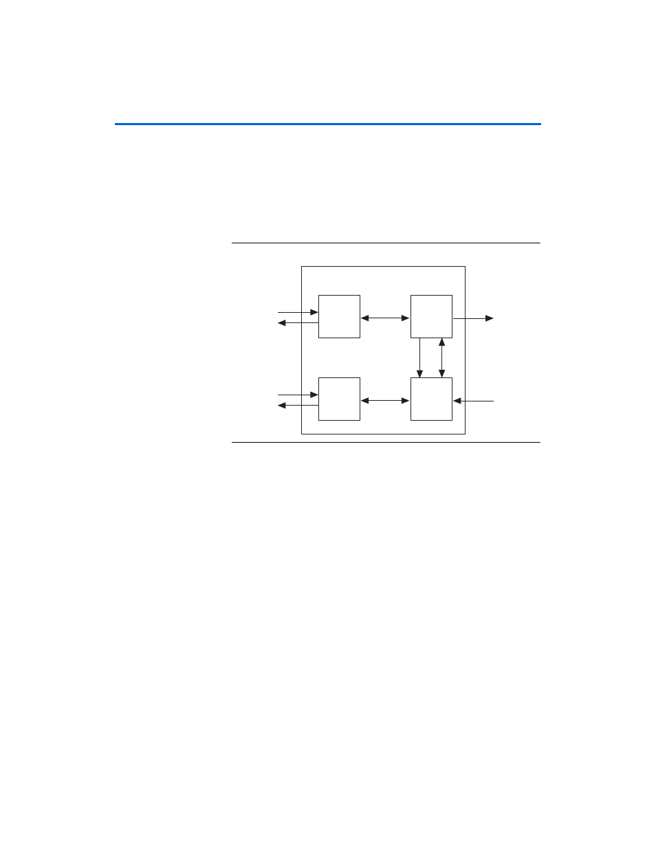
Control Logic
shows the control logic block diagram.
Figure 3–2. Control Logic Block Diagram
The basic architecture comprises two separate almost independent
channels. The write channel sends data to the memory. The read channel
receives the data. The address port on the QDRII SRAM interface is
shared— a write takes precedence when simultaneous reads and writes
occur. On the Avalon interface, all the signals are independent.
The write channel comprises an Avalon interface and a small pipeline to
perform two-cycle bursts. A finite state machine (FSM) controls the
signaling to the Avalon interface and deals with the data from Avalon
interface. The data and address are then passed to the I/O and sent to the
memory.
Similarly for the read channel, a FSM controls the signaling to the Avalon
interface and deals with the data going to Avalon interface. The read
command is passed to the QDRII SRAM interface and the data is
captured when arriving back. Simultaneous read and write operations
may lead to pauses on the Avalon read interface.
Avalon
Slave
Interface
Write
FSM
Avalon
Slave
Interface
Read
FSM
Pause
Control Logic
(Encrypted)