Board & controller – Altera QDRII SRAM Controller MegaCore Function User Manual
Page 63
Altera Corporation
MegaCore Version 9.1
3–31
November 2009
QDRII SRAM Controller MegaCore Function User Guide
Functional Description
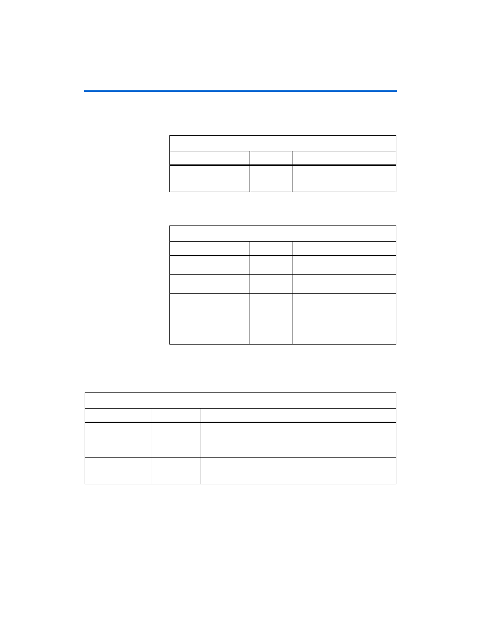
shows the local bus width parameter (only available with burst
length of four).
shows the memory interface parameters.
Board & Controller
shows the pipelining parameters.
Table 3–9. Local Bus Width Parameters
Parameter
Value
Description
Local bus width
Narrow mode
or wide mode
Narrow mode is twice the width of
the memory; wide mode is four
times the width of the memory.
Table 3–10. Memory Interface Parameters
Parameter
Value
Description
Device width
1 to 4
Specifies the number of devices to
increase the width of the data bus.
Device depth
1 to 2
Choose 2 to double the memory
space.
Use
altddio
pin
On or off
When turned on
altddio
outputs
generate the clock outputs. Turn off
to use dedicated PLL outputs to
generate the clocks, which is
recommended for HardCopy II
devices.
Table 3–11. Pipelining Parameters
Parameter
Value
Description
Number of pipeline
registers on address,
command, and data
outputs
0 to 4
You can choose 1, 2, or 3 pipeline registers between the memory
controller and the address, command, and data outputs. These
registers help to achieve the required performance at higher
frequencies.
Number of pipeline
registers on read data
0 to 4
You can choose 1, 2, or 3 pipeline registers between the memory
controller and the read data input. These registers help to achieve the
required performance at higher frequencies.