Altera QDRII SRAM Controller MegaCore Function User Manual
Page 57
Altera Corporation
MegaCore Version 9.1
3–25
November 2009
QDRII SRAM Controller MegaCore Function User Guide
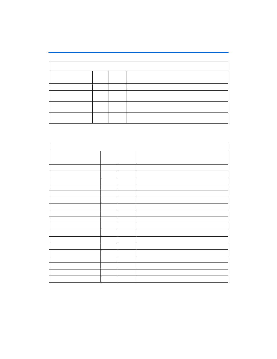
Functional Description
shows the datapath.
control_wpsn
–
Input
Write signal from the pipeline and resynchronization logic.
dll_delay_ctrl
5:0
Input
DLL delay control from the top-level design to shift the
CQ
by a
nominal 90 degrees.
capture_clock
–
Output
Capture clocks (CQ into soft logic) to the pipeline and
resynchronization logic.
captured_data
35:0
Output
Captured data—data after the IO to pipeline and
resynchronization logic.
Table 3–5. Datapath Interface Signals (Part 2 of 2)
Name
Width
(Bits)
Direction
Description
Table 3–6. Pipeline & Resynchronization Logic Signals
Name
Width
(Bits)
Direction
Description
avl_control_a_rd
17:0
Input
Read address from the control logic.
avl_control_a_wr
17:0
Input
Write address from the control logic.
avl_control_bwsn
3:0
Input
Byte enable from the control logic.
avl_control_rpsn
–
Input
Read from the control logic.
avl_control_wdata
35:0
Input
Write data from the control logic.
avl_control_wpsn
–
Input
Write from the control logic.
capture_clock
–
Input
Clocks from the datapath (CQ into soft logic).
captured_data
35:0
Input
Data captured by IO from datapath.
clk
–
Input
Clock.
reset
–
Input
Reset.
control_a_rd
17:0
Output
Read address to datapath.
control_a_wr
17:0
Output
Write address to datapath.
control_bwsn
3:0
Output
Byte enable to datapath.
control_rdata
35:0
Output
Read data after resynchronization to control logic.
control_rpsn
–
Output
Read to datapath.
control_wdata
35:0
Output
Write data to datapath.
control_wpsn
–
Output
Write to datapath.
training_done
–
Output
Initial training done to control logic.