Sdi audio extract parameters, Sdi audio extract parameters -5 – Altera SDI Audio IP Cores User Manual
Page 14
• A register interface block that provides support for an Avalon-MM control bus
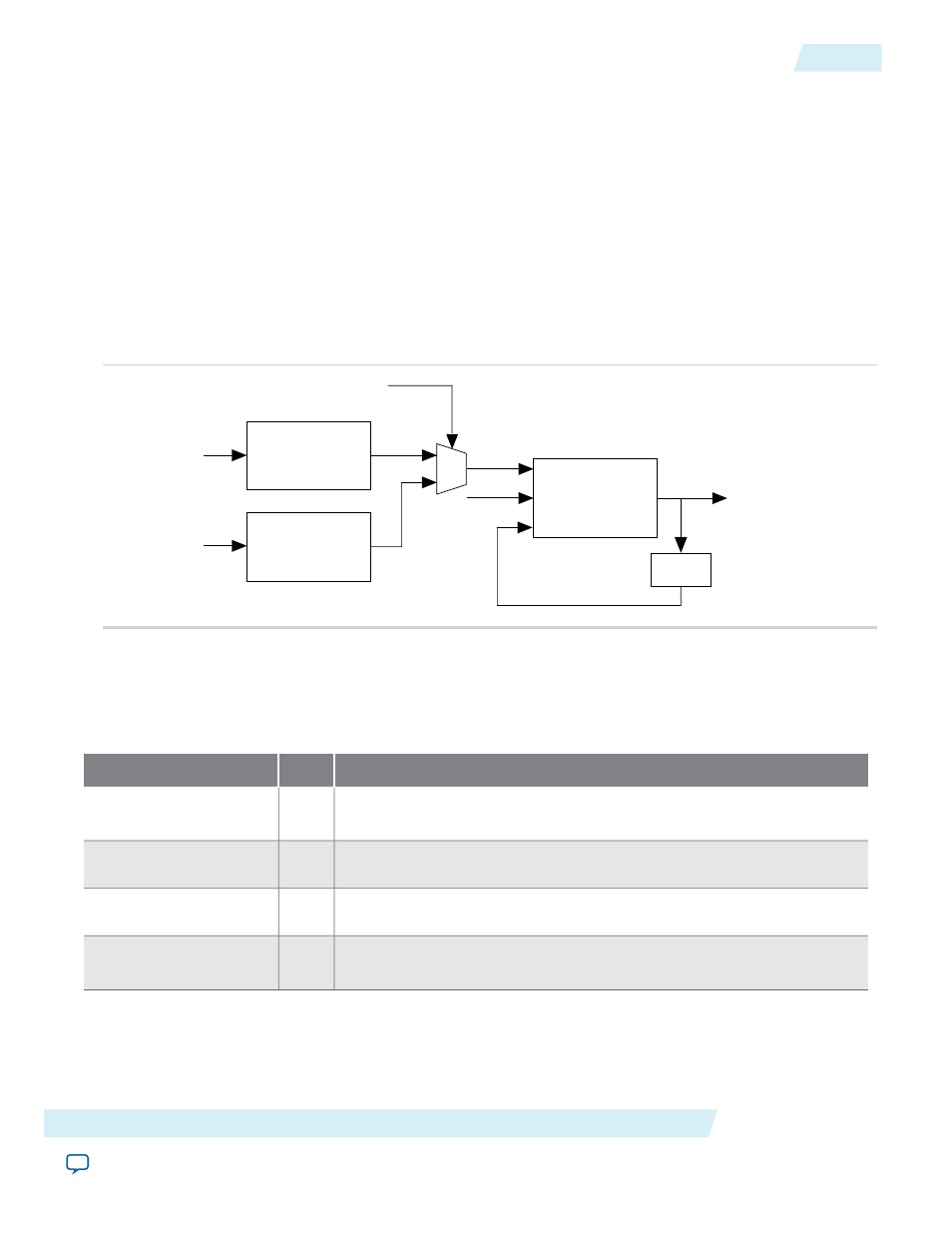
The clock recovery block recreates a 64 × sample rate clock, which you can use to clock the audio output
logic. As the component recreates this clock from a 200-MHz reference clock, the created clock may have a
higher jitter than is desirable.
A digital PLL synchronizes this created clock to a 24-kHz reference source.
For the HD-SDI embedded audio, the 24-kHz reference source is the embedded clock phase information.
For the SD-SDI embedded audio, where the embedded clock phase data is not present, you can create the
24-kHz reference signal directly from the video clock.
This figure shows the clock recovery block diagram.
Figure 3-3: Clock Recovery Block Diagram
Programmable
Divide
Digital
PLL
Clock Phase
Recovery
vid_clk
Video standard
3.072 MHz Output
24 KHz
200 MHz
Extracted
audio data
/128
SD
HD
SDI Audio Extract Parameters
The following table lists the parameters for the SDI Audio Extract IP core.
Table 3-2: SDI Audio Extract Parameters
Description
Value
Parameter
Enables the extra logic to recover the EDP ancillary packets from SD-SDI
inputs.
On or
Off
Include SD-SDI 24-bit
support
Turn on to store the received channel status data.
On or
Off
Channel status RAM
Turn on to enable extra error-checking logic to use the error status register.
On or
Off
Include error checking
Turn on to enable extra logic to report the audio FIFO status on the
fifo_
status
port or register.
On or
Off
Include status register
Altera Corporation
SDI Audio IP Functional Description
3-5
SDI Audio Extract Parameters
UG-SDI-AUD
2014.06.30