Altera SDI Audio IP Cores User Manual
Page 26
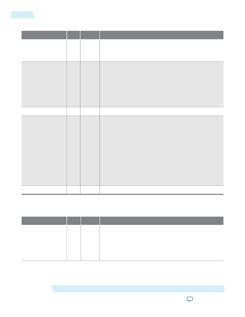
Table 4-8: SDI Audio Extract Video Input Signals
Description
Direction
Width
Signal
The video clock that is typically 27 MHz for SD-SDI, 74.25 MHz
or 74.17 MHz for HD-SDI, or 148.5 MHz or 148.35 MHz for 3G-
SDI standards. You can use higher clock rates with the
vid_
datavalid
signal.
Input
[0:0]
vid_clk
Indicates the received video standard. Applicable for 3G-SDI, dual
standard, and triple standard modes only.
Set this signal to indicate the following formats:
•
00b
for10-bit SD-SDI
•
01b
for 20-bit HD-SDI
•
11b
for 3G-SDI Level B
•
10b
for 3G-SDI Level A
Input
[1:0]
vid_std
Assert this signal when the video data is valid.
Input
[0:0]
vid_datavalid
This signal carries luma and chroma information.
SD-SDI:
• [19:10] Unused
• [9:0] Cb,Y, Cr, Y multiplex
HD-SDI and 3G-SDI Level A:
• [19:10] Y
• [9:0] C
3G-SDI Level B:
• [19:10] Cb,Y, Cr, Y multiplex (link A)
• [9:0] Cb,Y, Cr, Y multiplex (link B)
Input
[19:0]
vid_data
Assert this signal when the video is locked.
Input
[0:0]
vid_locked
This table lists the audio input and output signals.
Table 4-9: SDI Audio Extract Audio Input and Output Signals
Description
Direction
Width
Signal
Set this clock to 3.072 MHz that is synchronous to the extracted
audio.
For SD-SDI inputs, this mode of operation limits the core to
extracting audio that is synchronous to the video. For HD-SDI
inputs, you must generate this clock from the optional 48 kHz
output or the audio must be synchronous to the video.
Input
[0:0]
aud_clk
SDI Audio IP Interface Signals
Altera Corporation
UG-SDI-AUD
SDI Audio Extract Signals
4-6
2014.06.30