Caution – BINDER KB 23 User Manual
Page 73
KB (E3.1 + E5.1) 11/2014
page 73/100
CAUTION
Risk of short circuit.
Damage to the unit.
Use the supplied plug only (IP protection type 67). Plug it in and tighten it by screwing to
secure contact.
If the socket is not used, close the screw lid and turn it to secure.
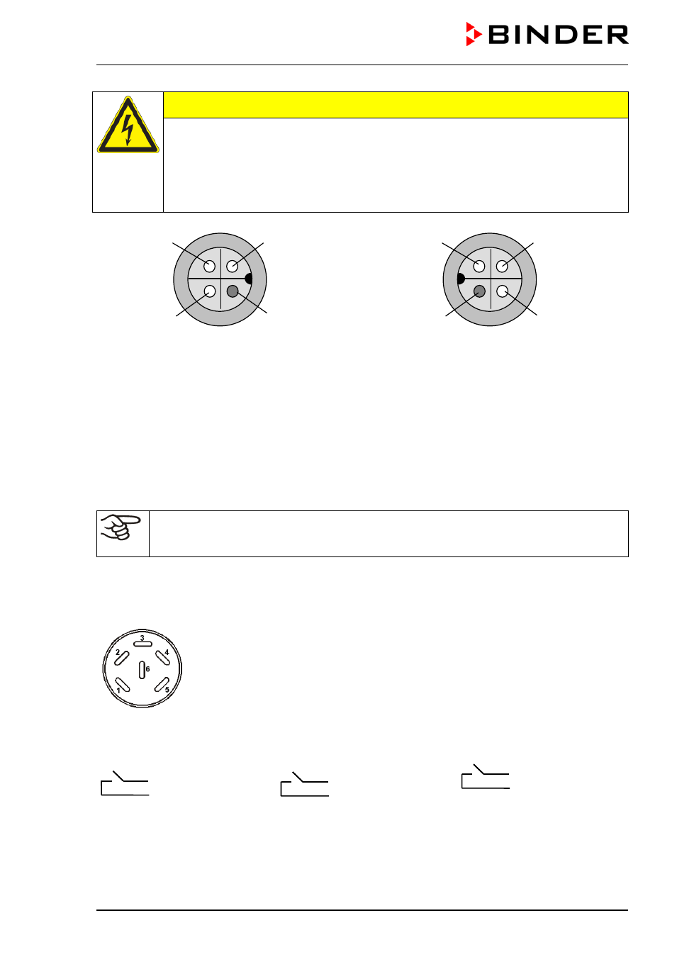
Figure 19: internal socket (front view)
Figure 20: Supplied waterproof plug (front view)
16.6 Zero-voltage relay outputs via operation lines (option from size 53 on)
Operation lines 1, 2 und 3 are used to switch any device connected to the zero-voltage relay outputs via a
DIN socket (8) in the right lateral control panel. The operation lines permit switching on and off the
individual zero-voltage relay outputs through the program controller. They can be programmed in fixed
value entry mode (chap. 6) as well as in the program editor (chap. 8.2) via the operation lines (switching
state
0 = Off, switching state 1 = On).
Deactivate the week program timer before entering set-points in fixed value entry mode (chap.
6) or before entering a program in the program editor (chap. 8). Otherwise, any setting of the
operation lines in fixed value entry mode or in the program editor is ineffective.
The connection is realized as a DIN socket.
With KB (E3.1) size 53 and 115, the DIN socket is located on the unit rear:
With KB (E5.1) size 240, 400 and 720, the DIN socket (8) is located in the right lateral control panel.
Figure 21: Pin configuration of the DIN socket(8) in the right lateral control panel
A suitable DIN plug is enclosed.
Operation line 1
Operation line 2
Operation line 3
Pin 1: Pin
Pin 2: Make
Pin 3: Pin
Pin 4: Make
Pin 5: Pin
Pin 6: Make
Switching state On:
1xx
Switching state On: x
1x
Switching state On: xx
1
Pin 1
Pin 2
PE
Pin 3
Pin 2
Pin 1
Pin 3
PE
1
2
1
2
5
6
3
4