Installation procedures – Pinnacle Systems DR User Manual
Page 19
12
Installation Procedures
DIN-rail Controller Module
WARNING: If you get a GREEN indication while the
test piece is in the curtain’s fi eld of view, this may be
due to any of the following reasons: (1) an incorrectly
sized test piece; (2) the Floating Blank option is
enabled and set larger than what you believe it to
be; or (3) there is a refl ection from adjacent refl ective
material. If #3 appears to be the case, you must
move the refl ective material further away from the
curtain or the curtain away from the material.
12) Install additional mechanical guards to prevent
anyone from getting to the hazardous point of
operation by reaching around, over, or under the
curtain. Also, to prevent anyone from getting in
between the curtain and the hazardous point
of operation, install L-shaped light curtains or
safety mats.
Aligning Pylons
Mechanically line up the pylons so they are looking
straight at each other. Twist the pylons to fi nd the
center of their sweet spot (the point at which you get
a solid GREEN indicator). If you are trying to run the
pylons close to the maximum operating distance, you
may have to tip one end of the Emitter pylons to get a
GREEN indication.
The diagnostics display will show the location of the
fi rst blocked beam. If you push the “FN1” button on the
Controller Module, the display will show you the location
of the next blocked beam. The last digit indicates how
many beams are blocked (see Appendix A: Diagnostics
& Troubleshooting for more details).
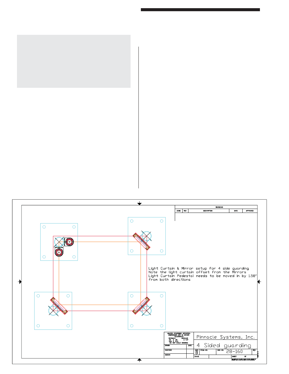
Aligning Mirrors
(refer to Figure 1)
Every mirror you add reduces the maximum operating
distance by -10% and also increases the diffi culty of
alignment. Because of the width of the mirrors and the
shoulders of the aluminum extrusion that protect the
mirror, you cannot turn a corner less than 90°.
The vertical height of the mirror with respect to the
vertical height of the pylons should be such that the
mirror matches the beam area of the pylons. You should
have some mirror showing above the top beam and
below the bottom beam.
All mirrors and pylons should be plumb. You should be
able to stand in front of one of the pylons, look straight
ahead, and see the other pylon through the center(s) of
the mirror(s). Depending on what the diagnostics display
reads, you may have to tip one end of the mirror to get
the remaining blocked beams to come in.
Installation Procedures
DIN-rail Controller Module
9
Figure 1: 4 Sided Guarding with Dual Stud Guard Brackets, TRM Mirrors and Model #8000 Pedestals