3 connectors, 1 vme connectors, Table 4-1 – Artesyn XMCspan Installation and Use (June 2014) User Manual
Page 36: Connector pin-outs, Controls, leds, and connectors
Controls, LEDs, and Connectors
XMCSPAN Installation and Use (6806800H03C)
36
4.3
Connectors
The XMCspan module connectors provide I/O and interfaces to the MVME7100 processor
modules and to other XMCspan modules.The pin assignments for the XMCspan connectors
are detailed in the succeeding sections.
4.3.1
VME Connectors
The VMEbus connector P1 is used for the XMCspan power supply. There is no connection to the
VMEbus except for signal SYSRESET#, which is connected to the on-board CPLD. The P1
connector also connects the following daisy chains:
IACKIN* and IACKOUT* with BG0IN* and BG0OUT*
BG1IN* and BG1OUT* and BG2IN* and BG2OUT* with BG3IN* and BG3OUT*
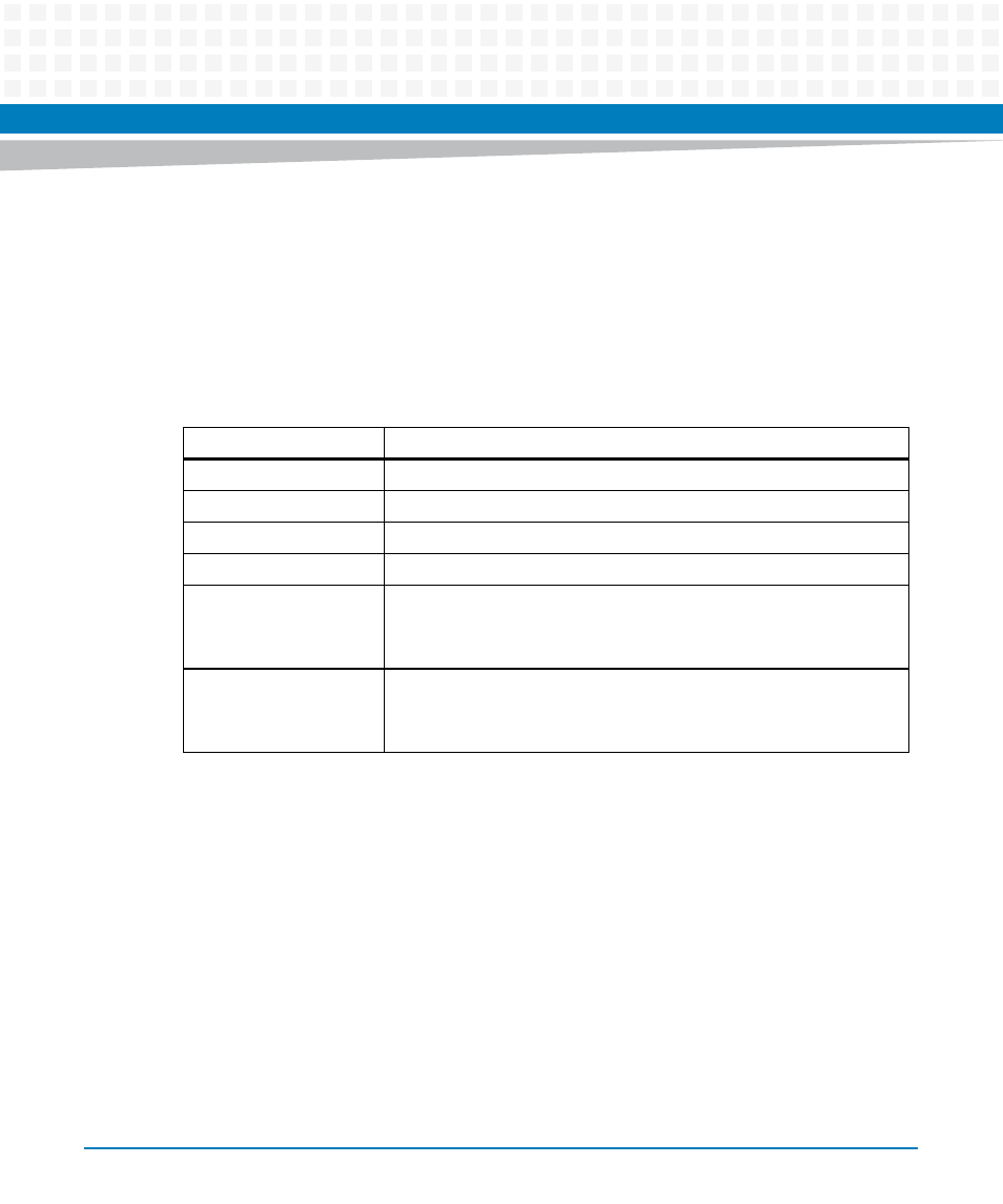
Table 4-1 Connector Pin-outs
Location
Function
P1
5-row VME connector.
P2
5-row VME connector.
J11 to J14, J21 to J24
PMC sites.
J15, J25
XMC sites.
P3
Connection to MVME7100
PCI Express expansion connector located on the bottom side
of the board.
J3
Connection to secondary XMCspan
PCI Express expansion connector located located on the top
side of the board.