2 led information, Table 4-3, Pex 8533 pcie switch – Artesyn XMCspan Installation and Use (June 2014) User Manual
Page 38: Controls, leds, and connectors
Controls, LEDs, and Connectors
XMCSPAN Installation and Use (6806800H03C)
38
4.3.2
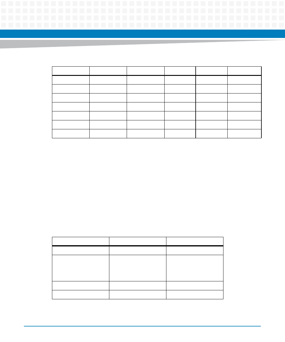
LED Information
The XMCSPAN has two front panel LEDs: PWR and RESET. The PWR LED is illuminated red if the
on-board supplies are not functioning properly. The PWR LED is off when the supplies are
good. The RESET LED is illuminated yellow if the board is in reset.The RESET LED is illuminated
green when not in reset.The XMCSPAN-001 has LEDs that are mounted on the surface of the
PWB and not visible from the front panel. The function of these LEDs is described in the tables
below.
26
GND
PMC1IO_52
-
PMC1IO_51
PMC2IO_39
27
PMC2IO_41
PMC1IO_54
-
PMC1IO_53
PMC2IO_40
28
GND
PMC1IO_56
-
PMC1IO_55
PMC2IO_42
29
PMC2IO_44
PMC1IO_58
-
PMC1IO_57
PMC2IO_43
30
GND
PMC1IO_60
-
PMC1IO_59
PMC2IO_45
31
PMC2IO_46
PMC1IO_62
GND
PMC1IO_61
GND
32
GND
PMC1IO_64
+5V
PMC1IO_63
VPC
Table 4-2 Pin definition for VME connector P2
Pin
Row Z
Row A
Row B
Row C
Ro
Table 4-3 PEX 8533 PCIE Switch
LED
Description
Color
D10
PEX_PORT_GOOD_0
Amber
D9
PEX_PORT_GOOD_1 (For
more details, refer
"Tsi384 PCIE-PCIX PMC2"
on page 39
Amber
D8
PEX_PORT_GOOD_2
Amber
D7
PEX_PORT_GOOD_8
Amber