Interconnections, Interconnections -5 – Basler Electric BE1-79A User Manual
Page 27
9310200990 Rev J
BE1-79A Functional Description
3-5
Interconnections
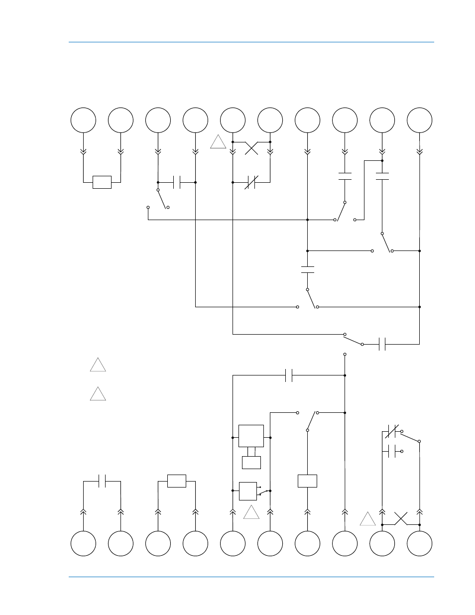
Figures 3-2 and 3-3 illustrate the interconnection of the contact sensing inputs, relay outputs, style
configuration switches, instantaneous reclose jumper switch, and RS contact configuration switch in the
BE1-79A relay. The state of all relay output contacts is shown with all power removed from the relay.
Figure 3-2 shows the relay configured for an ACR11A application. Figure 3-3 shows the relay configured
for an ACR11B application with an instantaneous recloser jumper.
Figure 3-2. Relay Interconnections for ACR11A Applications
11
12
13
14
15
16
17
18
19
20
1
2
3
4
5
6
7
8
9
10
C8
V1
V2
V3
C3
C10
C2
C4
C5
C7
C9
S3
S1
S1
S2
S2
S4
INT
EXT
A
B
B
A
C6
B
A
A
B
B
A
D2633-06
NC
NO
S5
V5
Power
Supply
RS
D
E
1
1
RS mode electronic selector
switch (SP-79ARS command)
2
2
2
Case-mounted, paddle-operated
shorting bars