Introduction, Instantaneous reclose testing, Acr11a style – Basler Electric BE1-79A User Manual
Page 53: Acr11b style, Acr11a and acr11b styles, Section 6 • testing -1, Introduction -1, Instantaneous reclose testing -1, Acr11a style -1, Acr11b style -1
9310200990 Rev J
BE1-79A Testing
6-1
SECTION 6 • TESTING
Introduction
You may prefer to test your relay before installation. To test BE1-79A relay functionality, perform the
procedures in the following paragraphs. Figure 6-1 illustrates the necessary connections for testing relays
configured for ACR11A style operation. The connections diagram for testing relays configured for
ACR11B operation is provided in Figure 6-2.
NOTE
The following test procedures specify 120 Vac for relay power and the contact
sensing inputs. Therefore, contact sensing jumpers P3, P4, P5, and P6 must
be set in position 1 or position 2. The contact sensing circuitry will not function
with 120 Vac applied and the contact-sensing jumpers setting position 3.
Instantaneous Reclose Testing
ACR11A Style
Place Relay Style Configuration switches S1, S2, and S3 in the A position. Place Instantaneous Reclose
Jumper switch S4 in the EXT position. Place RS Contact switch S5 in the NO position.
ACR11B Style
Place Relay Style Configuration switches S1, S2, and S3 in the B position. Place Instantaneous Reclose
Jumper switch S4 in the INT position. Place RS Contact switch S5 in the NO position.
ACR11A and ACR11B Styles
1. Place Test switch S1 in the 52a position and apply 120 Vac to the relay and test circuit.
2. Connect a PC with a serial port and suitable communication software to the relay serial port. Transmit
the settings of Table 6-1 to the relay.
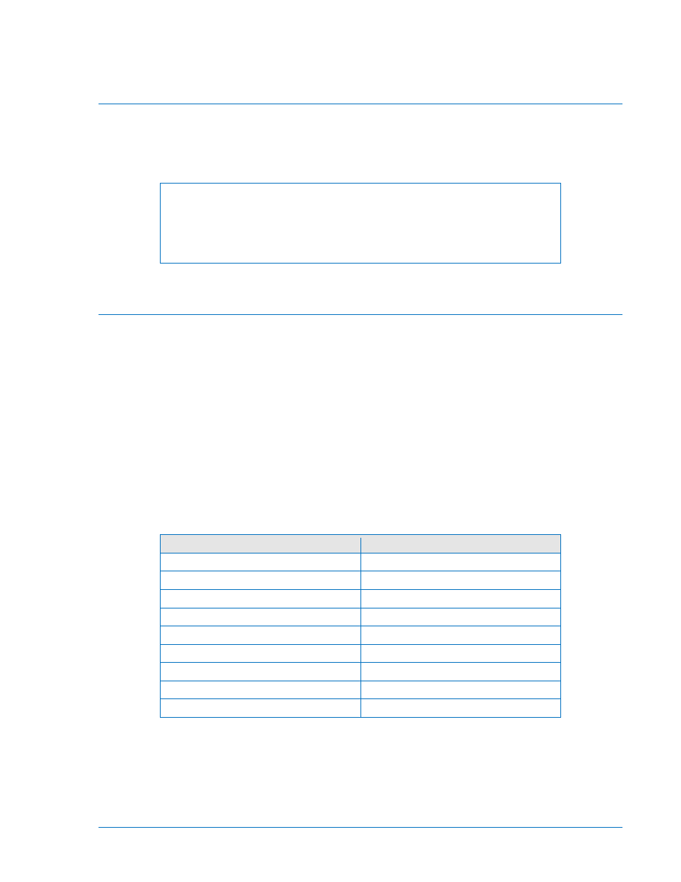
Table 6-1. Instantaneous Reclose Testing Commands
Command
Time Between Recloses
ACCESS=<cr>
N/A
SP-79A1=0.0,5.0<cr>
0 – 0 = 0s
SP-79A2=10.0,15.0<cr>
10 – 0 = 10s
SP-79A3=20.0,25.0<cr>
20 – 10 = 10s
SP-79A4=30.0,35.0 <cr>
30 – 20 = 10s
SP-79ALO=40.0,45.0<cr>
40 – 30 = 10s
SP-79ARS=D,19.39,0<cr>
N/A
EXIT<cr>
N/A
Y<cr>
N/A
3. Place Test switch S1 in the 52b position and observe that the following sequence of events occur.
a. Front panel Reset LED turns off
b. Reset indicator L1 turns off
c. Front panel In Sequence LED lights
d. Reclose indicator L2 will light immediately and remain lit for three seconds
e. After 10 seconds, L2 will light for three seconds