Control power connections, Communication connections, Serial communication – Basler Electric IDP-800 User Manual
Page 60
54
9437600990 Rev F
Control Power Connections
IDP-800 control power is provided by a suitably-sized, external 24 Vdc power supply. A power supply is
available from Basler Electric; request part number 9334503101.
The IDP-800 ground and control power wiring connects to the display panel through a three-conductor
connector that plugs into a jack located on the right side of the IDP-800. Figure 62 shows the location of
the IDP-800 control power jack. Figure 64 illustrates the wire assignments for the connector.
Figure 64. Control Power Connector Wire Assignments
When connecting the ground and control power wires to the connector, observe the following guidelines:
•
Use 18 to 12 AWG (0.75 to 2.5 mm
2
) solid-conductor or stranded-conductor wire
•
Strip each wire end so that 0.28 inches (7 millimeters) of conductor is exposed
•
Secure each wire to the connector using a small, flat-blade screwdriver. The recommended
connector screw torque is 5 to 7 in-lb (0.5 to 0.6 N
•m).
Communication Connections
Data and commands can be exchanged between the IDP-800 and DECS-200, DECS-200N, DECS-250,
DECS-250N, or DECS-400 using serial communication. In addition to serial communication, the
DECS-400 has the added capability of Ethernet communication with the IDP-800. When connected to an
Ethernet LAN, the display can be polled via Modbus to acquire data collected by the DECS connected to
the IDP-800.
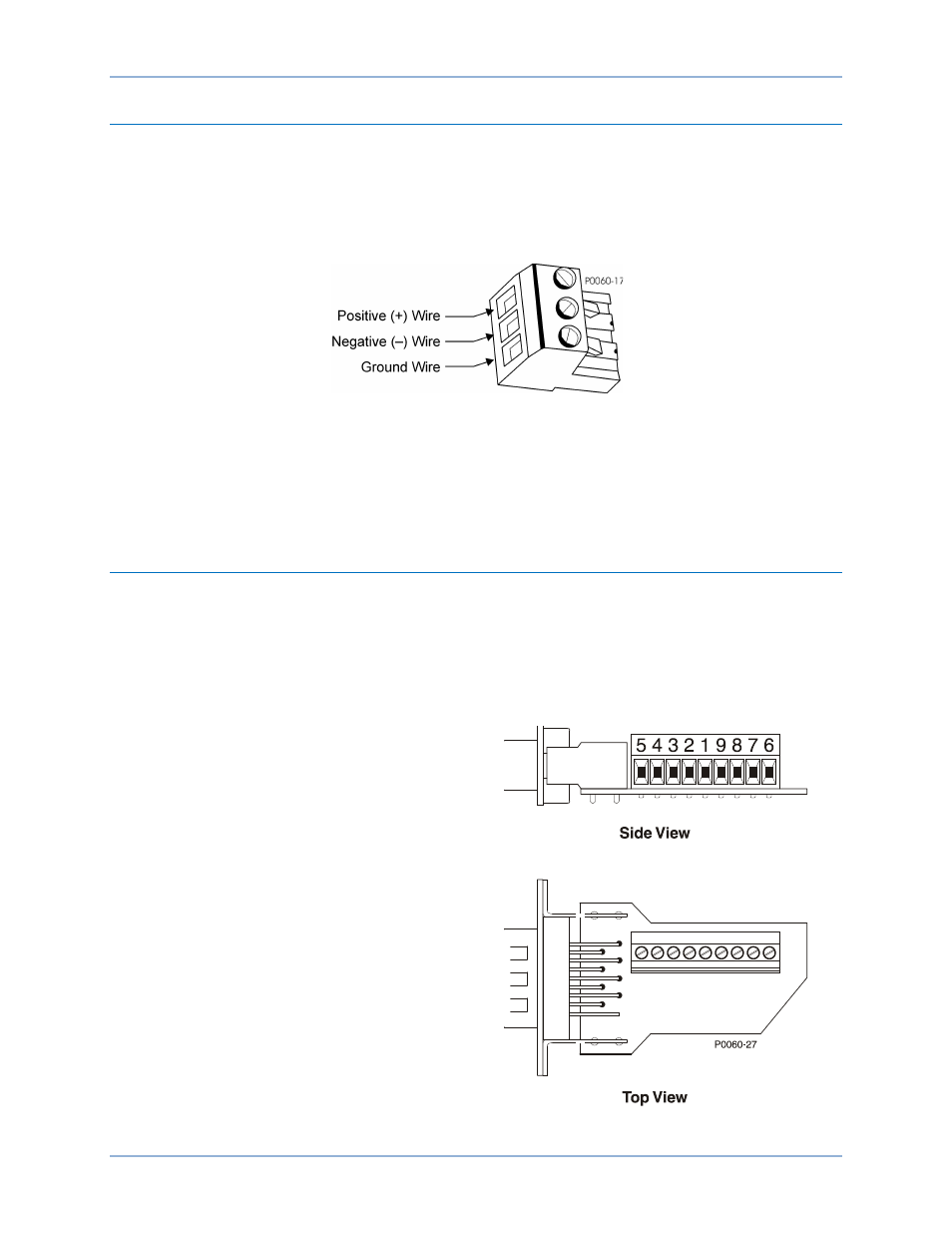
Serial Communication
Serial communication between a DECS and
IDP-800 requires the use of a terminal
conversion adaptor (Figure 65) that plugs
directly into the IDP-800. The adaptor, provided
with the IDP-800, consists of a nine-pin, D-sub
plug that mates with IDP-800 connector Com 2
(shown in Figure 65). A terminal block on the
adaptor provides connections for wiring to the
RS-485 (Com 2) terminals of the DECS and
jumpers required for IDP-800 communication.
Terminal block conversion adaptor connections
are illustrated in Figure 66. Connections
between the DECS and adaptor should be made
with twisted, shielded conductors.
See the Communication chapter for
communication setting and application
information.
Figure 65. Terminal Conversion Adaptor
Connections
IDP-800