7 button, 1 operating principle of the button – BECKHOFF CX210009x4 User Manual
Page 24
Product overview
2.7
Button
2.7.1
Operating principle of the button
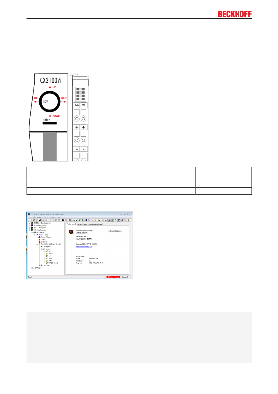
The CX11000xx4 power supply units all have four navigation switches and an Enter button. The buttons can
therefore be used to input five basic states
Button
Value
Button
Value
UP
4
RIGHT
32
DOWN
8
ENTER / SELECT
64
LEFT
16
Combined inputs, such as UP + RIGHT or UP + RIGHT + ENTER can also be entered. Each value is made
available separately as a boolean value and can be linked in the PLC.
The values of the button can be assessed as a numerical value via a TwinCAT function. A combination of
the buttons can also be assessed via the value. The register can be accessed from within a PLC program,
and the value can be assessed. This requires a variable of type USINT first to be created in the PLC
program. This is then called as a parameter in the ‘F_CXNaviSwitchUSB’ function. The code fragment shows
the declaration of the required variables.
PROGRAM MAIN
VAR
bUp AT %I* : BOOL;
bDown AT %I* : BOOL;
bLeft AT %I* : BOOL;
bRight AT %I* : BOOL;
bEnter AT %I*: BOOL;
bToggle AT %I* : BOOL;
Taster : USINT; (* als Summenwert *)
eNaviSwitchCx2 : E_CX2100_NaviSwitch;
END_VAR
CX210009x4
24
Version 1.1