Warning – Continental Fireplaces CDVS600 User Manual
Page 28
28
W415-0791 / C / 04.18.12
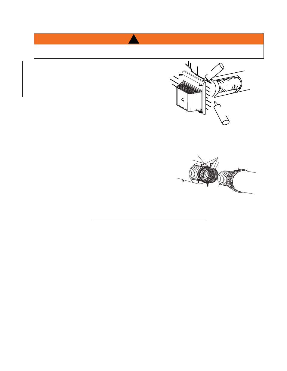
5.2.3 HORIZONTAL AIR TERMINAL INSTALLATION - MODEL CDVS600
A.
Stretch the inner fl ex pipe to the required length
taking into account the additional length needed for
the
fi nished wall surface. Apply a heavy bead of the
high temperature sealant W573-0007 Mill Pac (not
supplied) to the inner sleeve of the air terminal. Slip
the vent pipe a minimum of 2” over the inner sleeve
of the air terminal and secure with 3 #8 screws.
B.
Using the outer rigid pipe, slide over the outer combustion air
sleeve of the air terminal and secure with 3 #8 screws. Seal
using high temperature sealant W573-0002 (not supplied).
C.
Insert the vent pipes through the fi restop maintaining the required clearance to combustibles. Holding the air
terminal (lettering in an upright, readable position), secure to the exterior wall and make weather tight by sealing
with caulking (not supplied).
D.
From inside the house, using silicone, seal between the vent
pipe and the fi restop. Then slide the black trim collar over the
vent pipe up to the fi restop.
E.
If more vent pipe needs to be used to reach the appliance,
couple them together as illustrated. The vent system must be
supported approximately every 3 feet for both vertical and
horizontal runs. Use noncombustible strapping to maintain
the minimum clearance to combustibles.
The air terminal mounting plate may be recessed into the exterior wall or siding no greater than the depth of its
return fl ange.
23.7B
SCREWS
#10x2"
SEALANT
HIGH TEMP
2" OVERLAP
PIPE
4"FLEX
CAULKING
PIPE
7" RIGID
#8 X 1/2” SELF DRILLING
SCREWS & WASHERS
INNER COUPLER
OUTER COUPLER
HI-TEMP
SEALANT
OUTER
RIGID PIPE
INNER
FLEX PIPE
OUTER
RIGID PIPE
TERMINALS MUST NOT BE RECESSED INTO A WALL OR SIDING MORE THAN THE DEPTH OF THE
RETURN FLANGE OF THE MOUNTING PLATE.
!
WARNING