Pulley and crank shaft assembly – Cybex 525AT Arc Trainer User Manual
Page 33
33
Cybex Service Manual
Pulley and Crank Shaft Assembly
In this section you have the option to remove and install the following parts:
•
Crank covers
•
Shrouds
•
Control board
•
Crank arms
•
Crank shaft assembly
•
Counterweights
•
Lower pivot assembly
Tools Required
•
3/16” Allen wrench
•
7/32” Allen wrench
•
7/16” Socket wrench
•
1/2” Socket wrench
•
9/16” Socket wrench
•
7/32” Hex bit socket
•
3” Socket wrench extension
•
Cloth or rag (2)
•
9/16” Open end wrench
•
Torque wrench
•
Phillips screwdriver
•
Long Phillips screwdriver
•
Hammer
A cordless drill with a long Phillips bit is recommended but not required.
Elevate unit and disconnect power
1. Press the incline UP
key to level 20 incline.
WARNING: Shock and electrocution hazard
•
Unplug unit and let sit 10 minutes before cleaning or performing maintenance
•
Electrical charge can remain in unit after unplugging
•
Keep water and liquids away from electrical parts
2. Unplug the power cord from power outlet.
Remove linkage rods
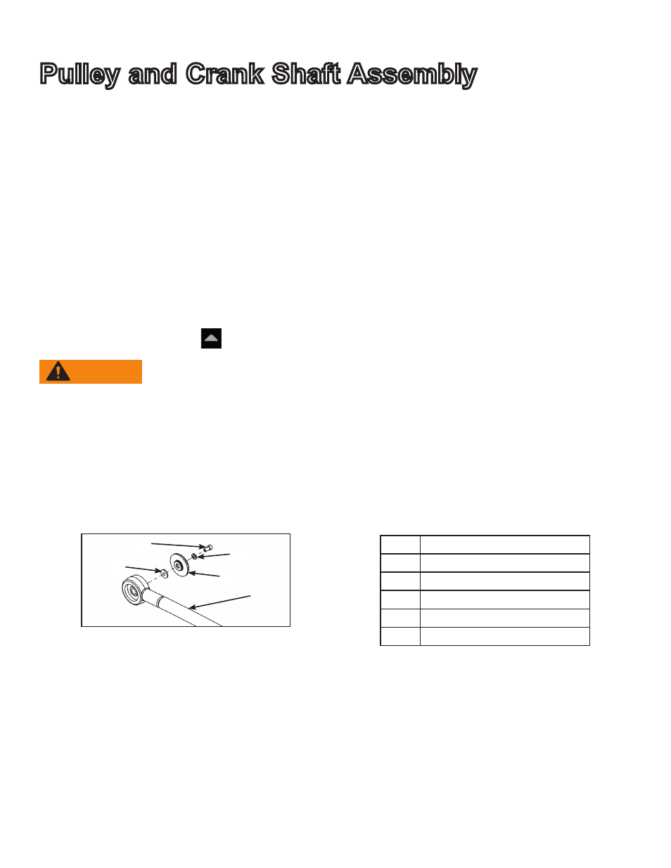
1. Remove the socket head cap screw (SHCS), flat washer, cap and spacer securing the linkage
rod using a 3/16” Allen wrench.
2
3
4
1
5
Description
1
Spacer
2
SHCS
3
Flat washer
4
Cap
5
Linkage rod
2. Lay the linkage rod down on the frame. Place a cloth in between the linkage rod and the frame
to prevent scratches.
3. Repeat steps 1 and 2 for other linkage rod.