Operational check – Daktronics C44 User Manual
Page 25
New Track
2-11
Installation
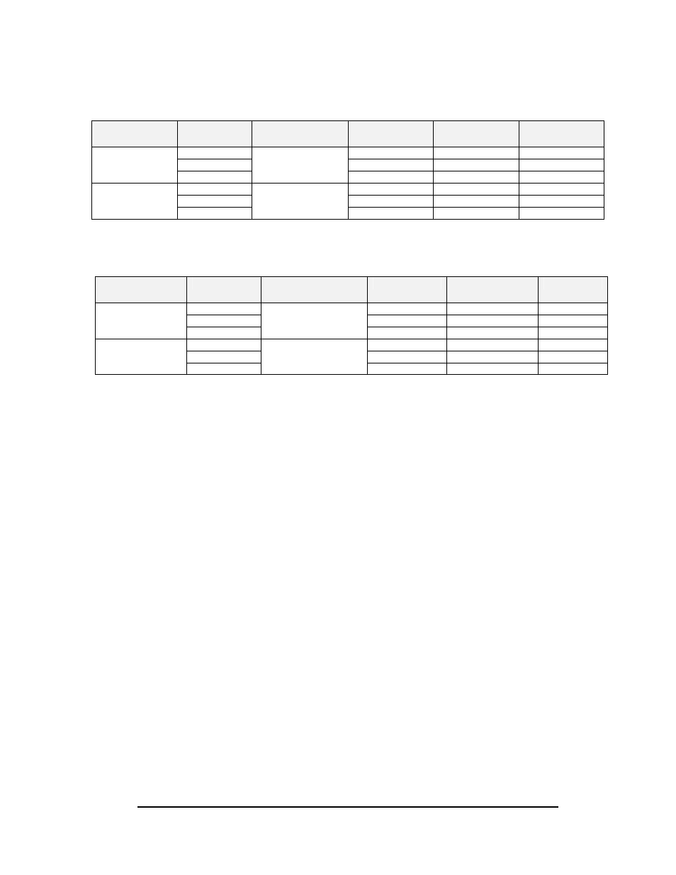
Isolation Interface to Left Scoreboard Wiring List
Description
From (I/I)*
Cable
Specifications
Wire Color
To (Left
Scbd)
Function
TB15-1 Red
TB31-1
SIG1-P
TB15-2 Black
TB31-2
SIG1-N
Left Lane SCBD
TB15-3
Beldon 8760
(Dak W-1117)
Shield Not
Connected Earth
TB15-1 Red
Tip
SIG1-P
TB15-2 Black
Ring
SIG1-N
Left Lane Dial-in
Display
TB15-3
Beldon 8760
(Dak W-1117)
Shield Not
Connected Earth
*Isolation Interface
Isolation Interface to Right Scoreboard Wiring List
Description
From (I/I)*
Cable
Specifications
Wire Color
To (Right
Scbd)
Function
TB15-4 Red
TB31-1
SIG2-P
TB15-5 Black
TB31-2
SIG2-N
Right Lane SCBD
TB15-6
Beldon 8760
(Dak W-1117)
Shield Not
Connected Earth
TB15-4 Red
Tip
SIG2-P
TB15-5 Black
Ring
SIG2-N
Right Lane Dial-
In Display
TB15-6
Beldon 8760
(Dak W-1117)
Shield Not
Connected Earth
*Isolation Interface
2.9
Operational Check
Reference Drawing:
Printer Interface Assy. ................................................................. Drawing A-65810
C-44Start Line J-Box ................................................................... Drawing A-75431
Field Cabling; C-44 Timer ......................................................... Drawing B-114631
During the operational check, the final connections are made on the system and preliminary
tests are done to determine if all the equipment is working properly. First, the equipment in
the tower is checked, then the start line, the intermediate equipment, and finally, the finish
line.
Timer - Monitor - Keyboard - Isolation Interface
This section will cover the connection of the equipment in the tower. Refer to the system
diagram and cabling diagram for information on the items that connect to the C-44. Refer
to Drawing A-65810 to view the back panel of the C-44.
Connect the cable that came with the video monitor to the "VIDEO BOARD
(VIDEO 1)" port on the back of the C-44. The power switch is on the lower
right side of the monitor.
Connect the cable that came with the keyboard to the "KEYBOARD" port.
Plug the C-44 and the monitor into a tower outlet. Other equipment will be
connected as the system is turned on.
Make sure the timer and monitor are plugged in. Turn on the power to the C-44
and monitor. Check to be sure the green power LED lights up when turned on
and the fan in the rear of the console is moving air. Make sure a clear picture of