Chapter 2 – DFI RL830-C602/C604 User Manual
Page 11
www.dfi.com
11
Chapter 2 Hardware Installation
Chapter 2
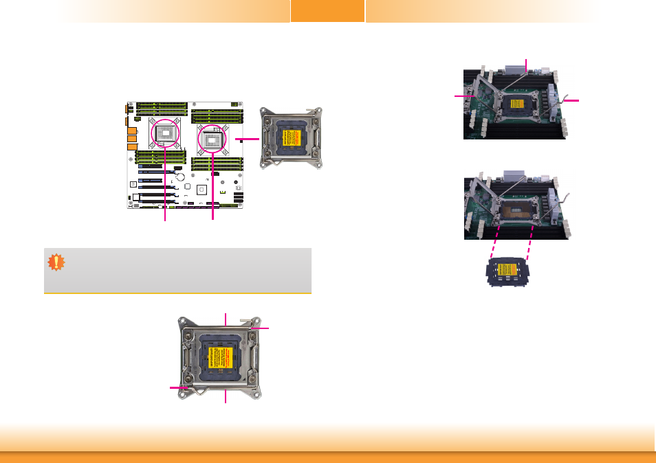
Important:
1. The CPU 0 socket must be populated first.
2. The CPU socket must not come in contact with anything other than the CPU. Avoid
unnecessary exposure. Remove the protective cap only when you are about to
install the CPU.
Installing the CPU
1. Make sure the PC and all other peripheral devices connected to it has been powered down.
2. Disconnect all power cords and cables.
3. Locate the LGA 2011
CPU socket on the sys-
tem board.
4. Unlock the socket by push-
ing the load lever down,
moving it sideways until it
is released from the reten-
tion tab; then lift the load
lever up.
Retention tab
Load lever
It must be released first.
6. Remove the protective cap
from the CPU socket. The
cap is used to protect the
CPU socket against dust
and harmful particles.
Remove the protective cap
only when you are about
to install the CPU.
5. Lift the load levers up to
the angle shown on the
photo and then lift the
load plate.
R227
U19
C170
7
6
R227
U19
C170
7
6
CPU 1
CPU 0
CPU 0 must be
populated first.
Load
plate
Load lever
Load lever
Protective cap
Load lever
Retention tab