Installing the dimm module, Chapter 2 – DFI RL830-C602/C604 User Manual
Page 9
www.dfi.com
9
Chapter 2 Hardware Installation
Chapter 2
The system board supports the following memory interface.
Single Channel (SC)
Data will be accessed in chunks of 64 bits (8B) from the memory channels.
Dual Channel (DC)
Data will be accessed in chunks of 128 bits from the memory channels. Dual channel provides
better system performance because it doubles the data transfer rate.
Quad Channel (QC)
Data will be expanded to 256 bits from the memory channels because it quadruples the avail-
able memory bandwidth to provide better performance.
Installing the DIMM Module
Single Channel
DIMMs are on the same channel.
DIMMs in a channel can be identical or
completely different. However, we highly
recommend using identical DIMMs.
Not all slots need to be populated.
Dual Channel
DIMMs of the same memory configuration
are on different channels.
Quad Channel
DIMMs in the same channel are identical.
Important:
When you are installing the memory modules on the system board, you must popu-
late them in the DDR3_1, DDR3_3, DDR3_5, DDR3_7, DDR3_9, DDR3_11, DDR3_13
or DDR3_15 sockets first.
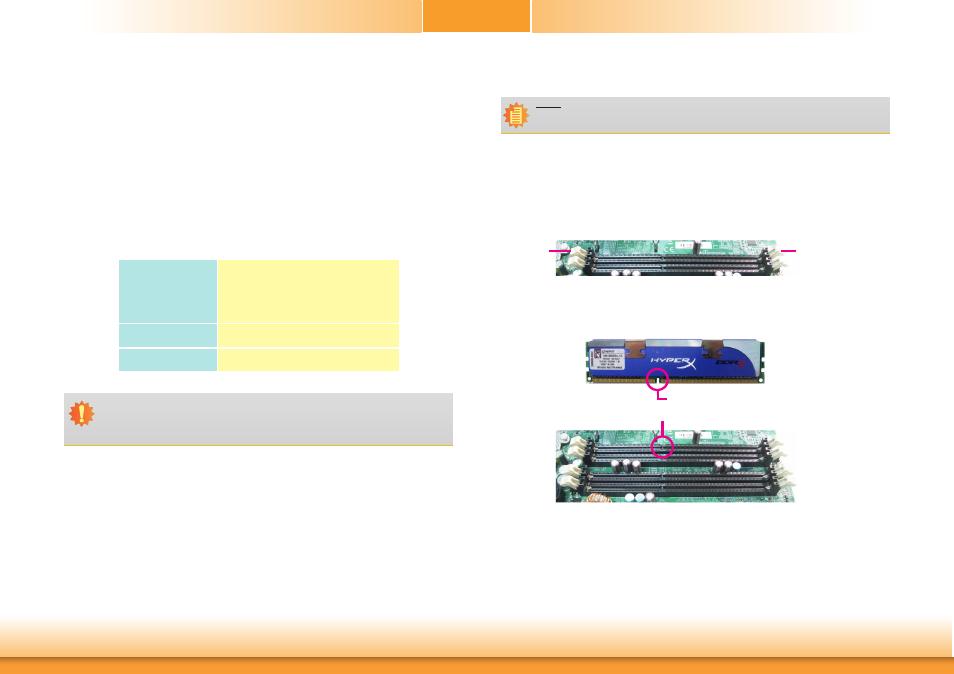
Note:
The system board used in the following illustrations may not resemble the actual
board. These illustrations are for reference only.
1. Make sure the PC and all other peripheral devices connected to it has been powered down.
2. Disconnect all power cords and cables.
3. Locate the DIMM socket on the system board.
4. Push the “ejector tabs” which are at the ends of the socket to the side.
Ejector tab
Ejector tab
5. Note how the module is keyed to the socket.
Key
Notch