Chapter 2 – DFI RL830-C602/C604 User Manual
Page 13
www.dfi.com
13
Chapter 2 Hardware Installation
Chapter 2
Installing the Fan and Heat Sink
The CPU must be kept cool by using a CPU fan with heat sink. Without sufficient air circula-
tion across the CPU and heat sink, the CPU will overheat damaging both the CPU and system
board.
1. Before you install the fan / heat sink, you must apply a thermal paste onto the top of the
CPU. The thermal paste is usually supplied when you purchase the fan / heat sink assem-
bly. Do not spread the paste all over the surface. When you later place the heat sink on
top of the CPU, the compound will disperse evenly.
Some heat sinks come with a patch of pre-applied thermal paste. Do not apply thermal
paste if the fan / heat sink already has a patch of thermal paste on its underside. Peel the
strip that covers the paste before you place the fan / heat sink on top of the CPU.
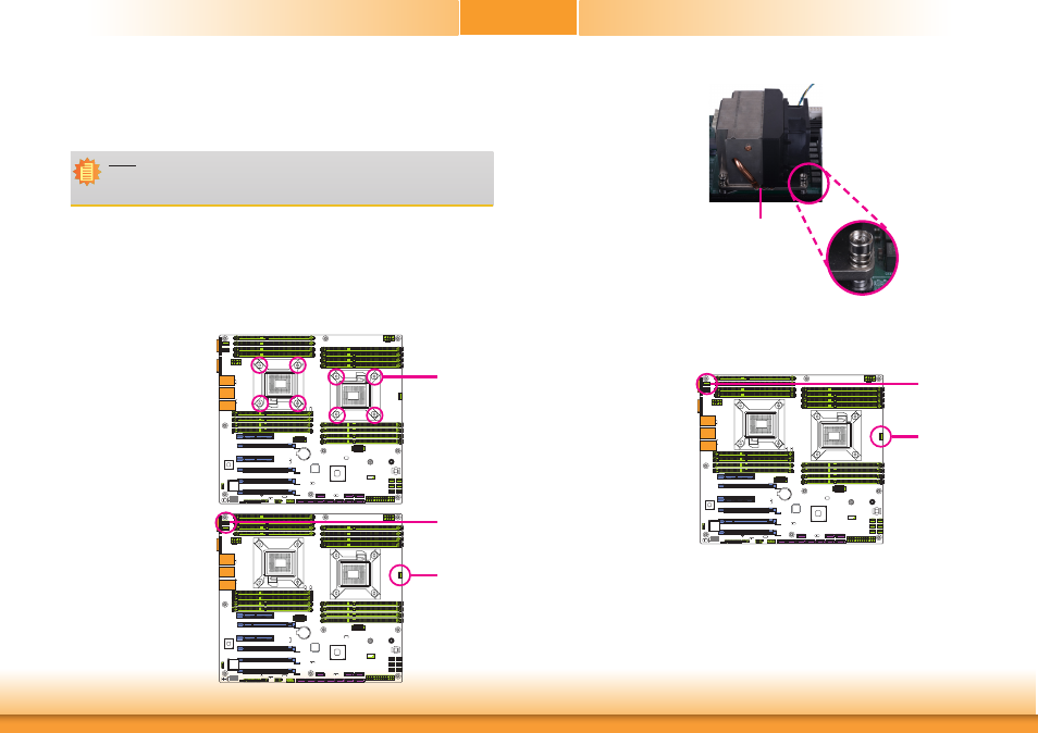
2. Place the heat sink on top
of the CPU. The 4 push-
pins around the heat sink,
which are used to secure
the heat sink onto the sys-
tem board, must match the
4 mounting holes around
the socket.
Mounting hole
3. Orient the heat sink such
that the CPU fan’s cable is
nearest the CPU fan con-
nector.
4. Rotate each push-pin ac-
cording to the direction of
the arrow shown on top of
the pin.
Push down two pushpins
that are diagonally across
the heat sink. Perform the
same procedure for the
other two push-pins.
5. Connect the CPU fan’s
cable to the CPU fan
connector on the system
board.
Note:
A boxed Intel
®
processor already includes the CPU fan and heat sink assembly. If your
CPU was purchased separately, make sure to only use Intel
®
-certified fan and heat
sink.
R227
U19
C170
7
6
R227
U19
C170
7
6
R227
U19
C170
7
6
R227
U19
C170
7
6
CPU Fan
connector
CPU Fan
connector
R227
U19
C170
7
6
R227
U19
C170
7
6
CPU Fan
connector
CPU Fan
connector
Heat sink
“Locked” position of
push-pin