Chapter 2 – DFI RL830-C602/C604 User Manual
Page 19
www.dfi.com
19
Chapter 2 Hardware Installation
Chapter 2
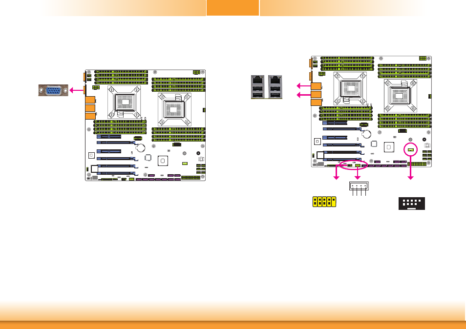
Graphics Interface
The display port consists of the following:
• 1 VGA port
VGA Port
The VGA port is used for connecting a VGA monitor. Connect the monitor’s 15-pin D-shell cable
connector to the VGA port. After you plug the monitor’s cable connector into the VGA port,
gently tighten the cable screws to hold the connector in place.
USB Ports
The USB device allows data exchange between your computer and a wide range of simultane-
ously accessible external Plug and Play peripherals.
The system board is equipped with eight onboard USB 2.0/1.1 ports (USB 0/4-5/6-7/10-12).
The 10-pin connector allows you to connect 2 additional USB 2.0/1.1 ports (USB 10-11). The
embedded USB connector (USB 0) is used for the eUSB SSD and the vertical USB port (USB
12) is the USB Drive Security for securing USB flash drive. The additional USB port may be
mounted on a card-edge bracket. Install the card-edge bracket to an available slot at the rear
of the system chassis and then insert the USB port cables to a connector.
BIOS Setting
Configure these onboard USB devices in the Advanced menu (“USB Configuration” submenu)
of the BIOS. Refer to the chapter 3 for more information.
USB 12
10
VCC
-Data +Data GND
Ke
y
VCC -Data +Data GND N.C.
9
1
2
USB 2.0
R227
U19
C170
7
6
R227
U19
C170
7
6
R227
U19
C170
7
6
R227
U19
C170
7
6
VGA
USB 2.0
USB 5
USB 4
USB 7
USB 6
USB 10-11
USB 0
USB 2.0
1
4
VCC
GND -Data +Data
10
2
1
9
+5VDU
+5VDU
GND
x x x
-Data +Data
HDD_LED
USB 2.0