Chapter 2 – DFI RL830-C602/C604 User Manual
Page 15
www.dfi.com
15
Chapter 2 Hardware Installation
Chapter 2
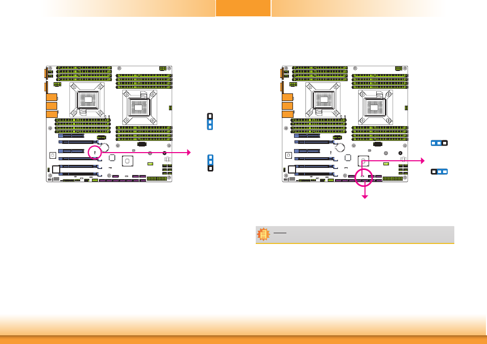
If you encounter the followings,
a) CMOS data becomes corrupted.
b) You forgot the supervisor or user password.
you can reconfigure the system with the default values stored in the ROM BIOS.
To load the default values stored in the ROM BIOS, please follow the steps below.
1. Power-off the system and unplug the power cord.
2. Set JP7 pins 2 and 3 to On. Wait for a few seconds and set JP7 back to its default setting,
pins 1 and 2 On.
3. Now plug the power cord and power-on the system.
2-3 On:
Clear CMOS Data
1-2 On: Normal
(default)
JP7
Clear CMOS Data
SATA DOM Power Select
2-3 On: +5V
1-2 On: GND
(default)
3
1 2
3
1 2
JP13
Note:
SATA port 4 provides adequate space for SATA DOM.
The JP13 is used to select the power of SATA DOM.
SATA 4
R227
U19
C170
7
6
R227
U19
C170
7
6
1
3
2
1
3
2
R227
U19
C170
7
6
R227
U19
C170
7
6