IHSE USA R434-91 Series SDLink Rackmount Hubs User Manual
Page 31
Remote Unit Configuration & Operation
29
6. Identify the ‘slowest’ color – the colored line furthest to the right. Delay the
signals of the two other colors using the following commands:
Delay Command
Key Sequence
Increase RED Delay (move right)
Decrease RED Delay (move left)
<R> + <Right Arrow>
<R> + <Left Arrow>
Increase GREEN Delay (move right)
Decrease GREEN Delay (move left)
<G> + <Right Arrow>
<G> + <Left Arrow>
Increase BLUE Delay (move right)
Decrease BLUE Delay (move left)
<B> + <Right Arrow>
<B> + <Left Arrow>
Use the Quick Skew feature to determine which color requires delaying or
to quickly set the delay on a color back to zero. Applying Quick Skew to a
color toggles its delay between zero and 19nS (a typically required value).
Quick Skew Command Key
Sequence
Toggle RED Delay
<Left Control> + <R>
Toggle GREEN Delay
<Left Control> + <G>
Toggle BLUE Delay
<Left Control> + <B>
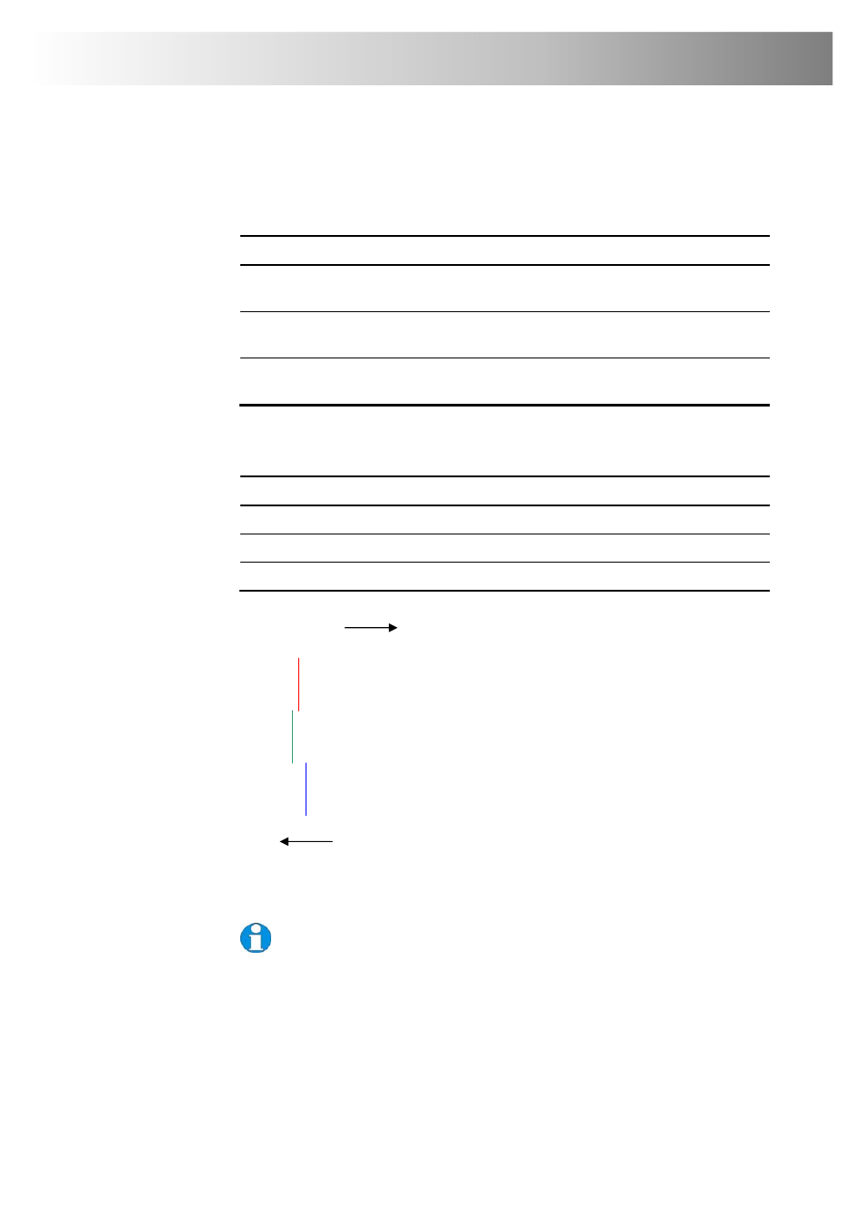
Figure 13 Illustration of skew and appearance on test card
Some Cat5e/Cat6 cables require a large green delay. Video quality can
often be vastly improved by using a standard cross-over patch cable at each
end of the link rather than a straight patch cable. For details see Appendix D:
Advanced Cabling Issues (Skew), page 51.
Sometimes the optimum skew adjustment will actually be one step out from that
suggested by the test card due to the way some monitors sample the signal.
The maximum amount of skew correction available is 42nS. This is more than
adequate for the vast majority of cables. However, it may not be enough if you are
using a particularly long run of a cable which exhibits severe delay skew.
Red
Green
Blue
Slower
Faster
In this illustration, Blue is the
slowest signal. To optimise the
image, Red and Green need to be
delayed until they align with Blue.