Ab c, Installation and operating instructions, Mounting tli to vpsc housing – Louroe Electronics DG-12II User Manual
Page 13
PAGE 10 of 28
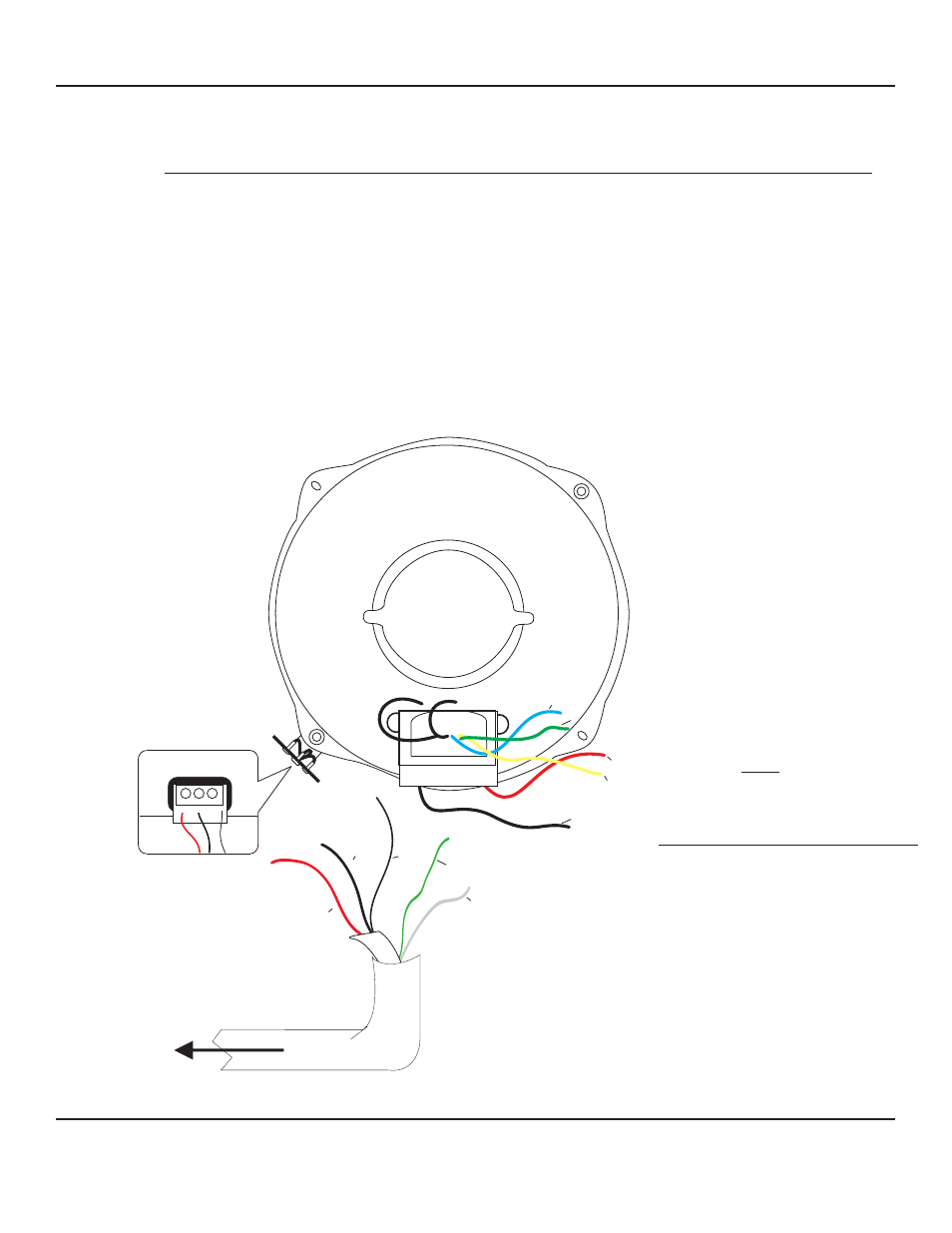
MICROPHONE AND SPEAKER CONNECTIONS (CONNECTIONS TO MODEL TLI):
Connect WEST PENN 356 (sample cable used) to remote station such as a Louroe TLI as
shown in Fig. 5 below. Connect the 3 wires wrapped with a shield (red, black and bare) to
microphone terminals marked “A”, “B”, and “C”. Red to “A”, black to “B” and bare or drain
wire to “C”. Connect the other two unshielded cables to speaker 70V transformer . Connect
green wire to proper transformer tap. See power tap table below for wattage. It is
recommended to use a lower wattage tap when two or more speakers are used or for “All
Call” function. Connect white wire to black wire of transformer, using wire nuts for
connections.
See Fig. 6 for connection diagram using model TLMC (speaker/microphone unit).
Fig. 5 Connection Diagram using TLI (speaker/microphone
A
B
C
A B C
Speaker Power Tap Table
Green Lead
70V
5 Watts
Yellow Lead
70V
2.5 Watts
Blue Lead
70V
1.25 Watts
Red Lead
70V
.62 Watts
Black Lead
70V
Common
A
B C
Drain
Red
Black
Red
Green
Yellow
White
Green
Blue
Mounting TLI to VPSC Housing
Place TLI inside VPSC matching the 4
mounting screws and secure with
furnished nuts and washers.
No knockouts are provided on the
VPSC. Bore a 3/4” opening through for
connecting to TLI.
To Louroe Audio Base Station
or other Audio Receiving Device
Black
Green Wire - of West Penn 356
connects to the proper power tap
White Wire - of West Penn 356
connects to Black wire from the TLI
Transformer using a wire nut.
DG_12II_6/11
LOUROE ELECTRONICS 6 9 5 5 VA L J E A N AVENUE, VAN NUYS, CA 91406
TEL (818) 994-6498
FAX
994-6458
website: www.louroe.com e-mail: [email protected]
(818)
®
INSTALLATION AND OPERATING INSTRUCTIONS