Installation and operating instructions, Paralleling two dg-12ii, Fig. 13 paralleling two dg-12ii’s – Louroe Electronics DG-12II User Manual
Page 21: Ii’s
PAGE18 of 28
PARALLELING TWO DG-12II
’s
:
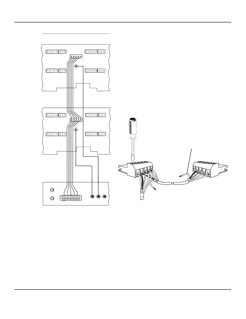
Two DG-12 units can be paralleled so that a zone can be
monitored and controlled from two different locations. See fig. 13
for interconnection diagram between two DG-12II’s and DG-MA.
See Fig. 14 for interconnecting the two plug-in connectors of two
DG-12II’s. Note that only one DG-12II gives power to the
remote microphone as shown by two end cables not connected.
The plug-in connector on the left hand side is the one giving
power to the remote station. No cable is connected to the “A”
terminal of the other connector. These plug-in connectors plug
into the Mic/Talkback 5-Pin Header[24] at the rear panel of the
respective DG-12II.
II
Fig. 13 Paralleling two DG-12II’s
Fig 14 Paralleling two plug-in connectors of two DG-12
II’s
INPUT
AUDIO
OUTPUT
1
2 3 4 5
ZONE 9
ZONE 10
ZONE 7
ZONE 8
ZONE 9
ZONE 10
ZONE 7
ZONE 9
“A” terminal not used
at second DG-12II
DG-MA
A
B C
SPG
A B C
SP G
DG12II #2
DG12II #1
DG_12II_6/11
LOUROE ELECTRONICS 6 9 5 5 VA L J E A N AVENUE, VAN NUYS, CA 91406
TEL (818) 994-6498
FAX
994-6458
website: www.louroe.com e-mail: [email protected]
(818)
®
INSTALLATION AND OPERATING INSTRUCTIONS