Installation and operating instructions, Rear of tlmc – Louroe Electronics DG-12II User Manual
Page 14
PAGE 11 of 28
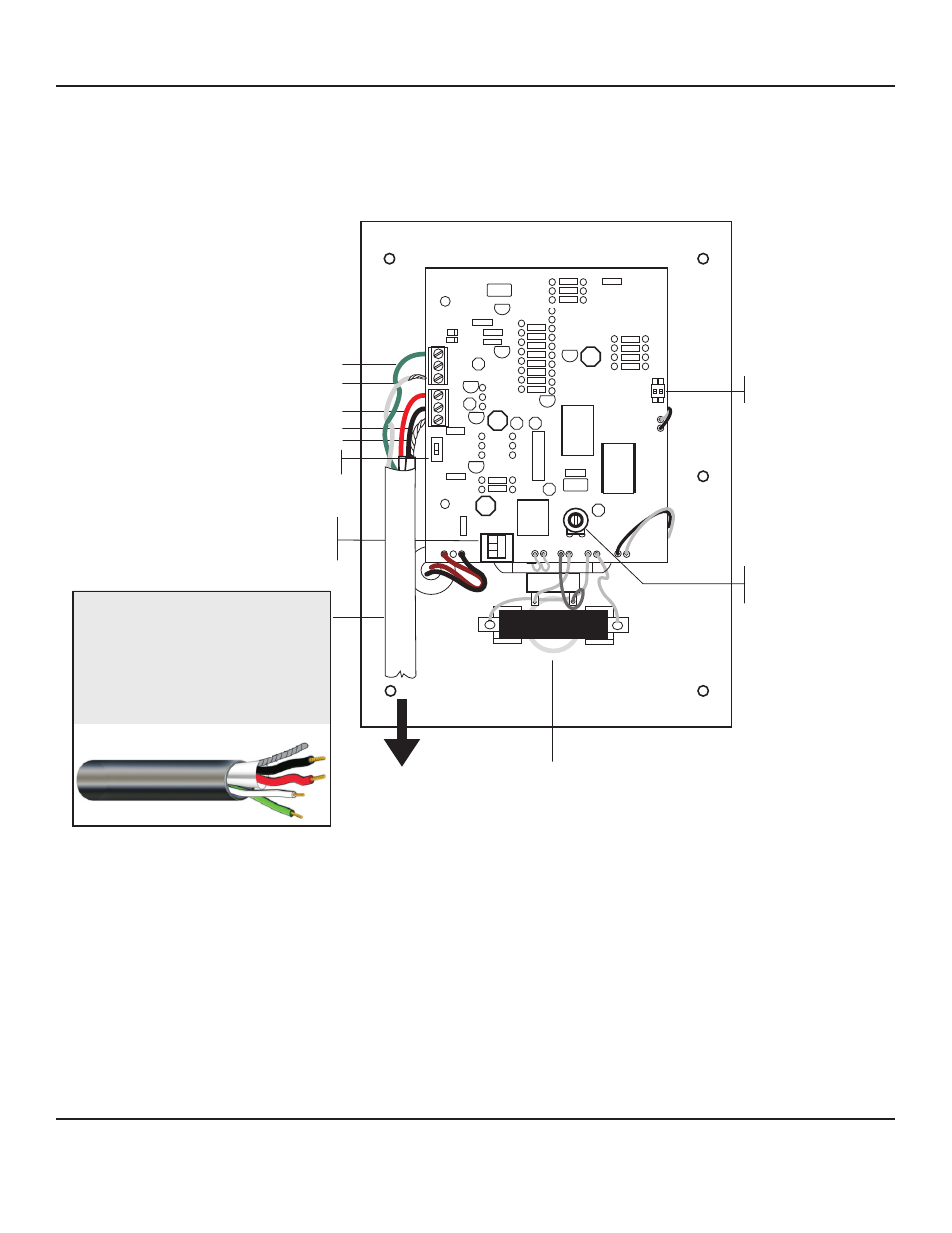
Fig. 6 Connection diagram using TLMC (speaker/microphone unit)
Rear of TLMC
Speaker Positive
Speaker Return Wire
MIC +12VDC Supply
MIC Audio
Ground
Normal or Timed Audio
Selector Switch
600 Ohm / 70 Volt
Selector Switch
Factory Set at 70V
To Base Station
Call Button
Time Selector
Dip Switch
Speaker Level Control
Factory Set
Do Not Adjust
SP
6
7
A
B
C
WIRING REQUIREMENTS
4 Conductor consisting of:
+ 2 Conductor shielded, 20 gauge
with 22 gauge drain (microphone
connection)
+ 2 Conductor unshielded, 18 gauge
(speaker connection)
All in the same jacket
West Penn 356 or equivalent
For two-way talk/listen applications
DG_12II_6/11
LOUROE ELECTRONICS 6 9 5 5 VA L J E A N AVENUE, VAN NUYS, CA 91406
TEL (818) 994-6498
FAX
994-6458
website: www.louroe.com e-mail: [email protected]
(818)
®
INSTALLATION AND OPERATING INSTRUCTIONS