1 omr mark layout, 2 omr positioning – MBM Corporation 49 User Manual
Page 24
T10114
Jan 2001
Sheet Feeder Model 49 Operator Manual
8-1
8. OMR
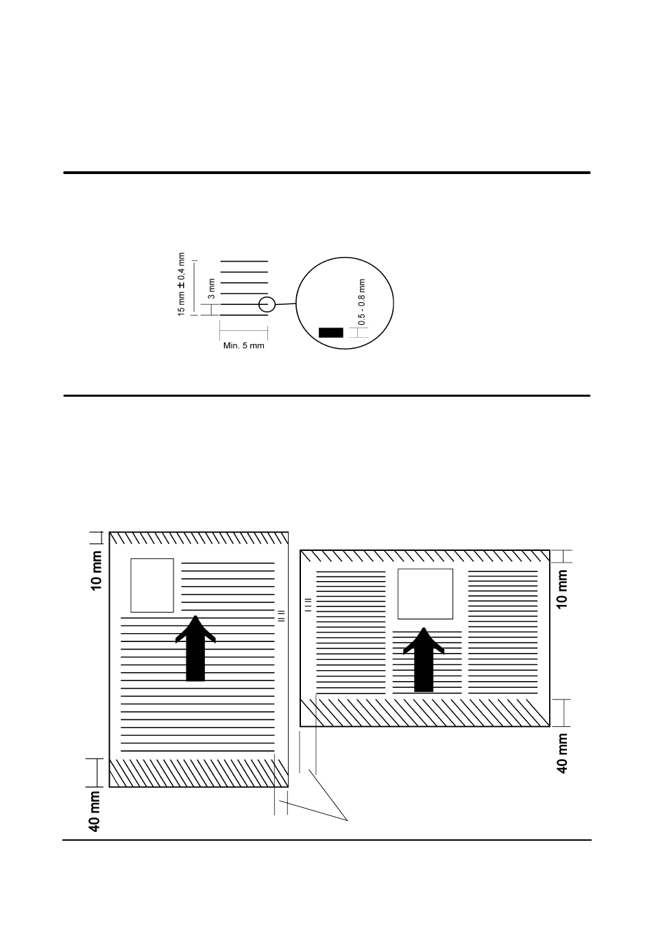
8.1 OMR mark Layout
The thickness of the marks should be between 0,5 to 0,8 mm (1½ – 2 pt). The length of the
marks should be 5 mm or more. The distance between the marks should be 3 mm. The length
of the total number of marks should be 15 mm ± 0,4 mm.
The OMR marks must not be printed within 10 mm from leading edge or 40 mm from trailing edge
of the sheet. Beside these limitations the OMR marks can be placed anywhere on the sheet. The
area covered by the OMR reader, between the leading edge and the OMR marks must be free from
text, images, and holes or similar in order not to confuse the reading procedure. Exception: A single
line before the OMR field, at least 10 mm away from the gate marks, will be ignored. Any print after
the OMR field will also be ignored. It is suggested that the margins on either side should be used for
placing the OMR marks. It is also advisable to place the OMR code closer to the leading edge
rather than the trailing edge, because of line-up reasons.
8.2 OMR Positioning
Area covered by OMR reader