Trimmer – MBM Corporation STITCHFOLD Trimmer User Manual
Page 14
14
Trimmer
ADJUSTMENTS
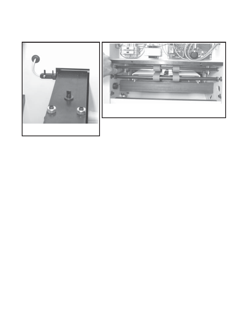
KNIFE BAR SENSOR ADJUSTMENT:
The knife bar must always stop at the top of it's
stroke in order for work to enter the trimmer. If
the knife bar stops too low work will not be able
to get past the front clamp and/or knife, and work
jams will result.
The function of the knife bar sensor is to signal the
control circuit when the knife bar has reached the
top of it's stroke so that the control circuit can
denergize the trimming clutch causing the knife
bar to stop at the top of it's stroke.
1. With power on and drive motor running, use
the knife change toggle switch to jog the knife
bar to the top of it's stroke. If you can not
stop the knife bar at exactly the top of it's
stroke, it is better to stop it slightly before top
of stroke rather than after top of stroke.
2. Turn off and unplug power.
3. Remove the left cover.
4. Loosen the screws of the knife bar sensor,
move the sensor so that the top of the sensor
is even with the top of the knife bar (fig 20).
5. Reinstall the left cover.
BACK STOP GATE ADJUSTMENT:
The function of the back stop gate is to provide a
surface for the work to square up against so that
the knife will cut the work squarely. The back
stop gate must be parallel to the bottom knife.
1. Run several pieces of work through the trim
cycle.
2. By looking at the work, determine how much
one side or the other of the back stop gate
must be moved forward or backward.
3. Turn off and unplug power.
4. Remove rear discharge table.
5. Remove rear upper cover.
6. Open top cover.
7. Slide backgage carriage to front of machine.
8. Using a 3/8" box wrench and a 1/8" hex
wrench loosen and shift one of the shoulder
screws (fig 21) locating the back stop gate
(which will also shift the back stop gate)
forward or backward the amount needed to
square up the trim. Note: It may be necessary
to first move one shoulder screw and then the
other in order to obtain the maximum amount
of adjustment.
9. Reinstall lower cover and discharge table.
(Fig 21)
(Fig 20)