Figure 19: b1 – solution, 3d nav field – NavCom StarUtil Rev.G User Manual
Page 33
StarUtil User Guide – Rev. G
When a message is set to On Change, the data is output each time new data is
available as determined by the Navigation Rate setting (see Figure 18). For
example, if a position is steadfast at N 33
º
50’20.18592” W 118
º
20’35.21218” for
three seconds and the Navigation Rate is 5Hz, a 0xb1 solution is output 1 time
because the position didn’t change. If any element of the position changes
continuously during the three second period then a 0xb1 solution is output 15 times.
The NMEA messages GGA, RMC, and VTG match the
output of the navigation rate up to 10 Hz max when
scheduled as On Change.
Min SVs for Solution: The default setting is three satellites.
Four satellites are the minimum SVs required for a 3D
navigation solution, plus an ac
ax PDOP for Solution: The maximum PDOP value at
nt on
satellites that can be "seen" by the receiver and the angle between the receiver
ed
s are
.
4-31
9
ceptable PDOP.
9
M
which the receiver will compute positions is 25.5. Enter the
highest PDOP value according to application requirements.
An applied value above 25.5 reverts to the default of 10.0.
The default setting for Max PDOP is 10. The quality of GPS data is depende
the geometry between the receiver and satellites; this includes the number of
and satellites as a constellation seen by the receiver. A s
usually provides a lower quality signal because of gr
interference and the increas
atellite near the
eater atmospheric
likelihood of the signal reflecting from surface
geometry on GPS
ion). PDOP is the overall
tellite geometry. For ex
a PDOP between 5 and 7 is
oor.
ermine how height will be
horizon
ample,
features; this is known as "multipath" error. The effect of
quality is measured by PDOP (position dilution of precis
measure of the precision obtainable with a given sa
a PDOP of 4 or less yields excellent precision,
acceptable and a PDOP of 7 or more is considered p
9
2D/3D Solution Mode: Click the Auto or Manual button to det
applied to a 2D navigation solution.
• Auto: Sets the receiver to automatically transition between 3D (4 satellite) and 2D (3
satellite) navigation. This can also be determined by DOP values, even if 5 satellite
available. In 2D navigation, the last valid computed height measurement is used
• Manual: Enter the Height hold value to set
the receiver to 2D (3 satellite) navigation
with the Height hold value used for the
height measurement. The receiver must
compute an initial 3D navigation solution
before it transitions to 2D navigation. After
2D navigation is established, the receiver
will not transition back to 3D navigation.
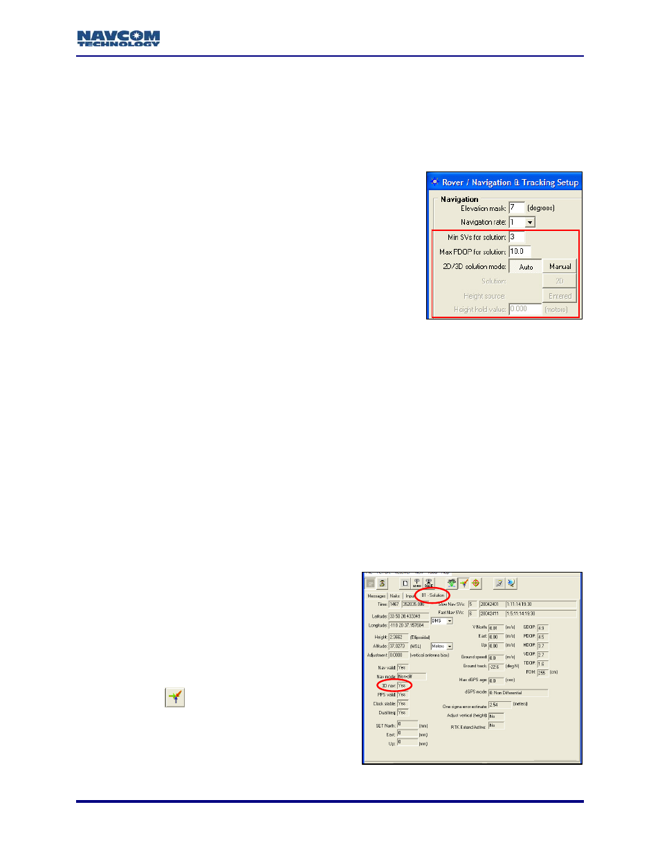
Click the
icon in the toolbar to view the
current navigation solution and other
Figure 19: B1 – Solution, 3D nav Field
parameters of message 0xB1. The 3D nav
field indicates if 3D navigation is computed
(see Figure 19).