Figure 21: vertical antenna bias, Figure 22: nct set, Figure 21) – NavCom StarUtil Rev.G User Manual
Page 35
StarUtil User Guide – Rev. G
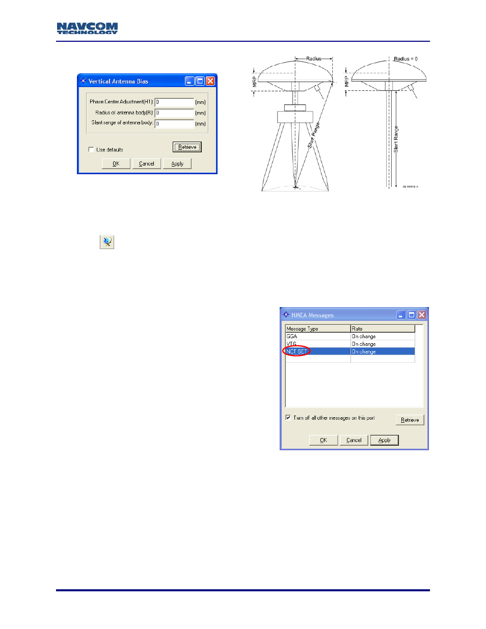
Figure 21: Vertical Antenna Bias
he Vertical Antenna Bias window from the main StarUtil window, click
the
To access t
icon or select Receiver > Setup > Vertical Antenna Bias.
9
Use Antenna Bias: Click the Yes or No button to determine if the values set in the Vertical
Antenna Bias window are applied to measurements.
9
Use SET Corrections: Click the Yes or No button to determine if Solid Earth Tide (SET)
corrections are applied to measurements.
Requirements for output of SET corrections:
• Message 0x49, W6 B6 set to Apply Correction
• NCT SET scheduled for output in the NMEA
Messages window (see Figure 22)
A license for the StarFire™ subscription service.
Figure 22: NCT SET
SET corrections to the position
, East, and Up corrections in millimeters
T provide better vertical
to account for gravitational effects
. the Sun, Moon, etc.).
output via the NMEA port is a NavCom proprietary NMEA type
s to the header, checksum, and electrical characteristics of a
standard NMEA string, but is not recognized by the NMEA governing body as an
•
The option, RTG input, must be set to Use on
the Rover / Tracking & Navigation Setup
window.
• Valid
Navigation
• Valid SET correctors (A minimum of 1 run of the
SET algorithm. These are an integral part of
StarFire™ corrections.)
If the criteria above are met, the receiver applies the
solution. The B1 Solution tab displays SET North
(see Figure 19, lower left corner).
SET refers to Solid Earth Tides. Positions with SE
(primarily) and horizontal positioning accuracy,
placed on terrain from celestial bodies (i.e
The SET message
message. It conform
4-33