ONICON F-5100 Insertion User Manual
Page 11
11451 Belcher Road South, Largo, FL 33773 • USA • Tel +1 (727) 447-6140 • Fax (727) 442-5699 • [email protected]
F-5100 Insertion Thermal Mass Flow Meter Manual 05/15 - 0663-20 / 18333
Page 11
SECTION 3.0: INSTALLATION, REMOVAL AND ADJUSTMENT
WARNING
Insertion flow sensors may be installed in pipes which are under high pressure or pipes filled with
combustible gases. Accidents with these systems can cause serious injury or death. Only persons
experienced with high pressure and/or combustible gas distribution systems and fluid sensoring
should attempt to install, adjust, or remove the flow sensor. Please read all instructions carefully
before attempting to install, remove or service a flow sensor.
ONICON will be happy to assist with technical recommendations and to provide guidance by phone
or e-mail. On-site field engineering, installation and service are also available at an additional cost.
3.1 INSTALLATION SITE SELECTION
Install the flow sensor where it will be accessible for personnel to perform necessary periodic
maintenance. The clearance required for installation is typically 30-36” from the pipe wall
to the nearest obstruction above the valve assembly. This clearance dimension will increase
with larger diameter pipes. Refer to Section 1.6 WORKING ENVIRONMENT for additional
considerations.
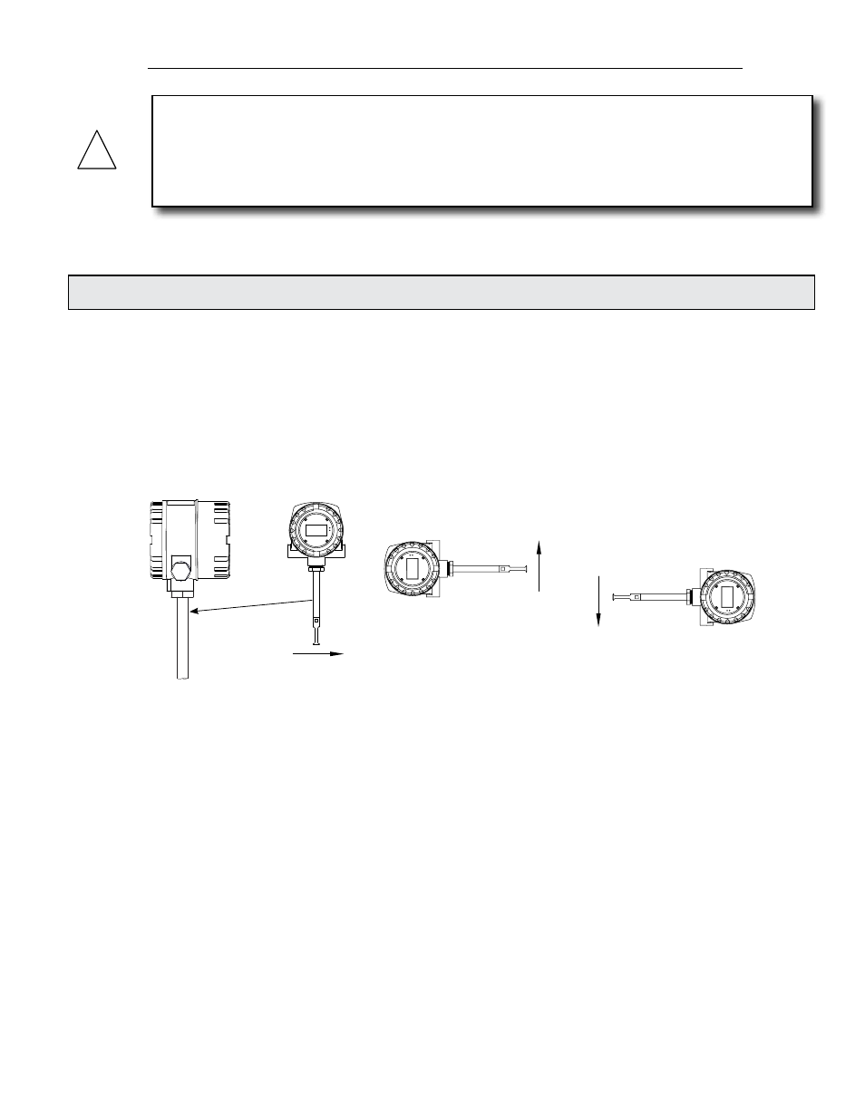
ONICON insertion style flow sensors must also be correctly oriented in the pipe with respect
to the direction of flow and the UPSTREAM mark on the stem. On sensors with an integrally
mounted display, this will affect the orientation of the display.
F-5000 Series
ONICON
Flow Direction
Flow Direction
Flow Direction
The drawings above illustrate the relationship between
flow direction and display orientation for standard meters.
F-5000 Series
ONICON
F-5000 Series
ONICON
The drawings above illustrate the relationship between the integral display, the flow direction
and the orientation of the sensor when installed in the pipe. Contact ONICON for assistance if
this relationship does not allow for viewing the display.
GENERAL PRACTICES:
1.
For best results, install the flow sensor in a straight run of pipe, free of bends, tees,
valves, transitions and obstructions.
2.
Straight run requirements vary based on the nature of the upstream obstruction.
See the table on page 13 for guidelines in determining upstream straight run
requirements. Depending upon specific location details, more or less straight run
may be required to produce a satisfactory flow profile.
3.
If there is insufficient straight run, allow 80% of the run upstream and 20% of
the run downstream. If the total length of straight run is less than 75% of the
recommended distance, performance may seriously degrade, and consideration
should be given to installing a flow conditioner.
!
F-5000 Series
F-5000 Series
F-5000 Series
ONICON
ONICON
ONICON
Flow Direction
Flow Direction
Flow Direction
The drawings above illustrate the relationship between
flow direction and display orientation for standard meters.
UPSTREAM