ONICON F-5100 Insertion User Manual
Page 8
11451 Belcher Road South, Largo, FL 33773 • USA • Tel +1 (727) 447-6140 • Fax (727) 442-5699 • [email protected]
F-5100 Insertion Thermal Mass Flow Meter Manual 05/15 - 0663-20 / 18333
Page 8
1.5 ADDITIONAL HARDWARE THAT MAY BE REQUIRED
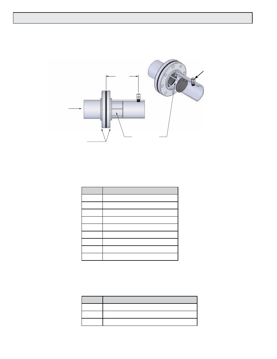
1.5.1 Flow Conditioners
Flow conditioners may be required when an insufficient straight run of pipe is available
upstream of the proposed sensor location. ONICON provides flow conditioners as an
optional accessory.
ONICON flow conditioners are designed to be installed between two flanges (provided
by installer) that are located a specific distance upstream of the flow sensor. The use of
flow conditioners significantly reduces the upstream straight pipe length requirement
for flow sensor. See page 12 for straight run requirements. The size of the flow conditioner
must match the pipe size. Contact ONICON for Schedule 80 flow conditioners.
Part #
Description
17381
1” Flow Conditioner, Sch40
17382
1¼” Flow Conditioner, Sch 40
17383
1½” Flow Conditioner, Sch40
17384
2” Flow Conditioner, Sch40
17385
2½” Flow Conditioner, Sch40
17386
3” Flow Conditioner, Sch40
17387
4” Flow Conditioner, Sch 40
17388
6” Flow Conditioner, Sch40
17389
8” Flow Conditioner, Sch40
1.5.2 Additional Remote Mount Cable
ONICON remote mount sensors are provided with 25 ft of cable. Additional cable lengths
of up to 1000 ft may be added without affecting the calibration of the sensor.
Part #
Description
17350
25 ft of additional mount remote cable
17351
50 ft of additional remote mount cable
17352
100 ft of additional remote mount cable
Largest of the
two perforated
plates
Gaskets
FLOW
ANSI class flanges
(user supplied)
2 pipe
diameters
Flow conditioning
assembly is
inserted here
Flow sensor
inserts here