5 remote mount wiring remote sensor wiring detail – ONICON F-5100 Insertion User Manual
Page 22
11451 Belcher Road South, Largo, FL 33773 • USA • Tel +1 (727) 447-6140 • Fax (727) 442-5699 • [email protected]
F-5100 Insertion Thermal Mass Flow Meter Manual 05/15 - 0663-20 / 18333
Page 22
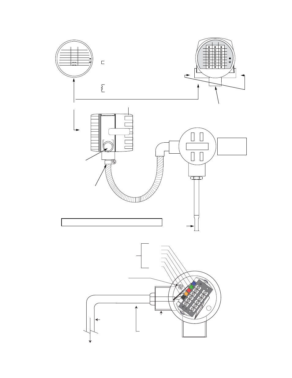
3.5.5 Remote Mount Wiring
Remote Sensor Wiring Detail
INSIDE BODY VIEW
INSIDE REAR
COVER LABEL
A1 - RED - VELOCITY SENSOR WIRE (HEATED ELEMENT)
A2 - GREEN - SENSE WIRE
A3 - BLUE - VELOCITY SENSOR WIRE (HEATED ELEMENT)
A4 - WHITE - TEMPERATURE SENSOR WIRE
A5 - BLACK SENSE WIRE
A6 - ORANGE - TEMPERATURE SENSOR WIRE
B1 - AC1 - AC VOLTAGE
B2 - AC2 - AC VOLTAGE
B3 - NU - NOT USED
B4 - 4 - 20 mA POWER
B5 - VDC IN - VOLTAGE DC - POSITIVE (+)
B6 - VDC GND - VOLTAGE DC - GROUND (-)
C1 - NOT USED
C2 - RS 485 (+)
C3 - RS 485 (-)
C4 - 24 VDC PULSE - 0 TO 24 DC PULSE OUTPUT
C5 - 4 - 20 mA - 4 TO 20 mA ANALOG OUTPUT
C6 - VDC GND - VOLTAGE DC - GROUND (-)
FLOW
½” NPT
USER ENTRY
FOR WIRING
1
2
3
4
5
6
1
2
3
4
5
6
A
B
C
1
RED
AC1
COM
1
2
GREEN AC2
B +
2
3
BLUE NU
A –
3
4
WHITE NU
4
5
BLACK
4-20mA
5
6
ORANGE
SIG GND
6
A
B
C
24 VDC
PULSE
VDC IN
+
VDC GND
–
REMOTE
JUNCTION BOX
JUNCTION BOX
CONTAINS NO
ELECTRONICS,
JUST TERMINALS
¾” NPT FOR
REMOTE CABLE
*
*
Factory installed jumper and resistor. Do not remove.
*
½” NPT
USER ENTRY
FOR WIRING
(ONE ON EACH SIDE)
TERMINAL BLOCK SIDE
NO CUSTOMER ACCESS
DO NOT OPEN THIS SIDE
¾” FNPT FOR
Conduit Connection
DISPLAY SIDE
Remote Cable
Blue
Green
Red
Orange
Black
White
Ground Screw
Metal conduit
is recommended
with appropriate
grounding to
minimize effects
from external
noise sources.
Interconnect Cable
¾” NPT
conduit connection
To Terminal A1 to A6
shown above