Setting insertion depth with gage, Tightening compression fitting, Tightening the compression fitting – ONICON F-5100 Insertion User Manual
Page 29: Caution, Warning, Low pressure high pressure
11451 Belcher Road South, Largo, FL 33773 • USA • Tel +1 (727) 447-6140 • Fax (727) 442-5699 • [email protected]
F-5100 Insertion Thermal Mass Flow Meter Manual 05/15 - 0663-20 / 18333
Page A-2
Compression
Fitting
3) Confirm upstream mark is aligned with flow and hand
tighten compression fitting. Refer to other side of tag for
tightening instructions.
2) Insert flow meter until bottom of electronics case touches
top of depth gage.
Depth Gage
1) Pierce insulation (if present) until gage tip touches pipe.
3) Confirm upstream mark is aligned with flow and hand
tighten compression fitting. Refer to other side of tag for
tightening instructions.
2) Insert flow meter until bottom of electronics case touches
top of depth gage.
1) Pierce insulation (if present) until gage tip touches pipe.
Insulation
Pipe
TIGHTENING COMPRESSION FITTING
CAUTION
!
Compression Fitting
Reducer Bushing
Ball Valve
Close Nipple
Weld-on Branch Outlet
1
4) Once the compression fitting is tight, position top and bottom
locking collars as shown. Tighten both to complete installation.
1) Insert the meter as described on the other side of this tag.
2) Tighten the nut until the stem will not turn by hand or move axially in the fitting.
3) Mark the nut at the 6 o’clock position.
4) While holding the fitting body steady, tighten the nut one and one quarter (1 ¼)
turns to the 9 o’clock position.
Depth Gage
Insulation
Pipe
Compression
Fitting
Top & Bottom
Collar
LOW PRESSURE
HIGH PRESSURE
SYSTEM MAY BE UNDER HIGH PRESSURE. When inserting, removing or adjusting the meter
meter from the pipe causing serious injury. The hand effort required to hold the meter will be 0.2
times the pipe pressure.
!
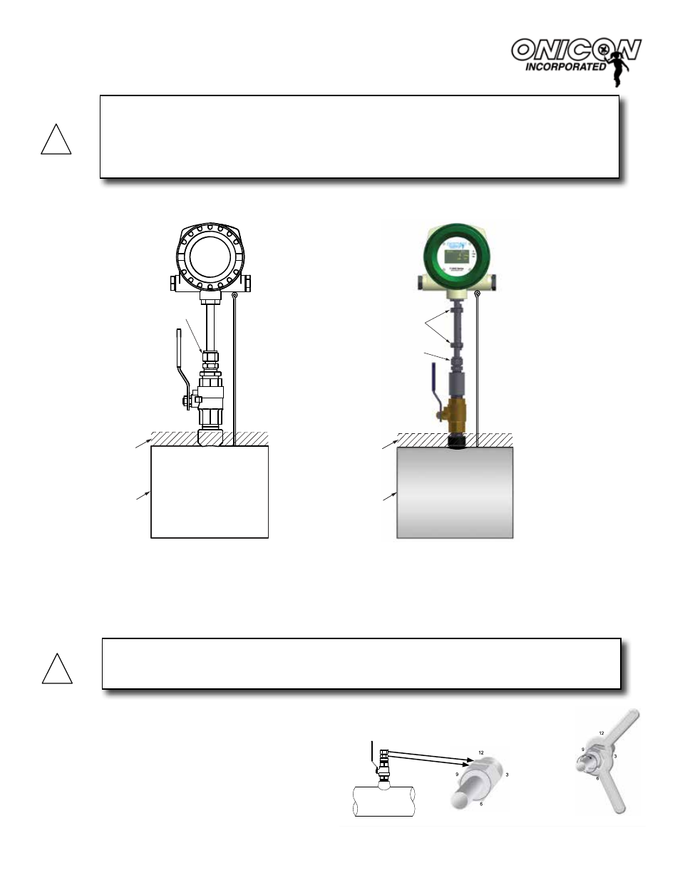
SETTING INSERTION DEPTH WITH GAGE
Compression
Fitting
3) Confirm upstream mark is aligned with flow and hand
tighten compression fitting. Refer to other side of tag for
tightening instructions.
2) Insert flow meter until bottom of electronics case touches
top of depth gage.
Depth Gage
1) Pierce insulation (if present) until gage tip touches pipe.
3) Confirm upstream mark is aligned with flow and hand
tighten compression fitting. Refer to other side of tag for
tightening instructions.
2) Insert flow meter until bottom of electronics case touches
top of depth gage.
1) Pierce insulation (if present) until gage tip touches pipe.
Insulation
Pipe
TIGHTENING COMPRESSION FITTING
CAUTION
!
Compression Fitting
Reducer Bushing
Ball Valve
Close Nipple
Weld-on Branch Outlet
1
4) Once the compression fitting is tight, position top and bottom
locking collars as shown. Tighten both to complete installation.
1) Insert the meter as described on the other side of this tag.
2) Tighten the nut until the stem will not turn by hand or move axially in the fitting.
3) Mark the nut at the 6 o’clock position.
4) While holding the fitting body steady, tighten the nut one and one quarter (1 ¼)
turns to the 9 o’clock position.
Depth Gage
Insulation
Pipe
Compression
Fitting
Top & Bottom
Collar
LOW PRESSURE
HIGH PRESSURE
SYSTEM MAY BE UNDER HIGH PRESSURE. When inserting, removing or adjusting the meter
meter from the pipe causing serious injury. The hand effort required to hold the meter will be 0.2
times the pipe pressure.
!
LOW PRESSURE
HIGH PRESSURE
1) Pierce insulation (if present) until gage tip touches pipe.
2) Insert flow sensor until bottom of electronics case touches top of
depth gage.
3) Confirm upstream mark is aligned with flow and hand tighten
compression fitting. Refer to instructions below to tighten fitting.
1) Pierce insulation (if present) until gage tip touches pipe.
2) Insert flow sensor until bottom of electronics case touches top of
depth gage.
3) Confirm upstream mark is aligned with flow and hand tighten
compression fitting. Refer to tightening instructions below.
4) Once the compression fitting is tight, position top and bottom
locking collars as shown. Tighten both to complete installation.
TIGHTENING THE COMPRESSION FITTING
1) Insert the sensor as described above.
2) Tighten the nut until the stem will not turn by hand or move axially in the fitting.
3) Mark the nut at the 6 o’clock position.
4) While holding the fitting body steady, tighten the nut one and one quarter
(1¼) turns to the 9 o’clock position.
CAUTION
The compression fitting must be tightened as described in the following procedure. Failure to do
will likely result in fluid leaks and/or permanent damage to the flow sensor stem.
!
WARNING
SYSTEM MAY BE UNDER HIGH PRESSURE. When inserting, removing or adjusting the sensor
position, be sure to hold the enclosure firmly by hand before SLOWLY loosening the
compression fitting. Failure to do this will allow the pressure to suddenly and rapidly force the
sensor from the pipe causing serious injury. The hand effort required to hold the sensor will be 0.2
times the pipe pressure.
!