ONICON F-5100 Insertion User Manual
Page 14
11451 Belcher Road South, Largo, FL 33773 • USA • Tel +1 (727) 447-6140 • Fax (727) 442-5699 • [email protected]
F-5100 Insertion Thermal Mass Flow Meter Manual 05/15 - 0663-20 / 18333
Page 14
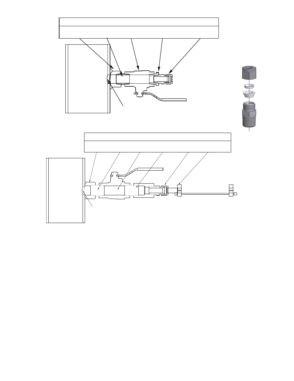
INSTALLATION KIT COMPONENTS
¾” WELD-ON
¾” CLOSE
¾” FULL PORT
¾” CLOSE ½” COMPRESSION WELDMENT WITH
BRANCH OUTLET
NIPPLE
BALL VALVE
NIPPLE
FITTING
CABLE & COLLARS
5/8” MINIMUM DIA
ACCESS HOLE
3.2.2 Directions For Standard Installation (During New Construction)
1.
Identify an appropriate location for the flow sensor.
2.
Weld the branch outlet onto the pipe.
3.
Drill a 5/8 inch (minimum) access hole, centered in the branch outlet.
4.
Install the close nipple, ball valve, reducer bushing (or close nipple and
weldment) and compression fitting as shown above; use a paste type thread
sealant or Teflon® tape as needed.
5.
Flush and pressurize the system.
3.2.3 Directions For Hot Tap Installation (A Pressurized System)
1.
Identify an appropriate location for the flow sensor.
2.
Weld the branch outlet onto the pipe.
3.
Install the close nipple and ball valve as shown below; use a paste type thread
sealant or use Teflon® tape.
4.
Use a hot tap drilling machine to create the 5/8” access hole.
5.
Remove the drill and clear all debris from the valve.
6.
Install the reducer bushing and compression fitting (or weldment and
compression fitting) using paste type thread sealant or Teflon tape as needed.
50 PSIG Maximum Pressure
500 PSIG Maximum Pressure
G
G
L
L
¾”
NPT BRANCH
¾”
CLOSE
¾”
FULL PORT
¾”
TO
½”
REDUCER
½”
COMPRESSION
OUTLET
NIPPLE
BALL VALVE
BUSHING
FITTING
INSTALLATION KIT COMPONENTS
⅝”
MINIMUM DIA
ACCESS HOLE
(Exploded view)
Compression
Fitting