Important notice – ONICON F-5100 Insertion User Manual
Page 12
11451 Belcher Road South, Largo, FL 33773 • USA • Tel +1 (727) 447-6140 • Fax (727) 442-5699 • [email protected]
F-5100 Insertion Thermal Mass Flow Meter Manual 05/15 - 0663-20 / 18333
Page 12
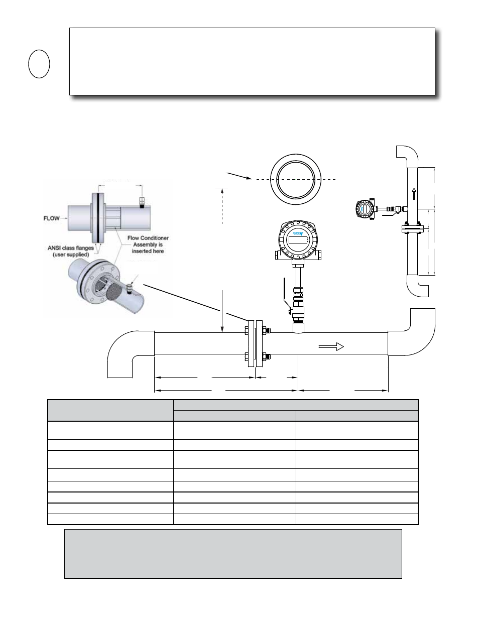
In addition to the information provided above and on the previous page, the following diagram
and table should be used as a guide to the proper location for installing the sensor.
Upstream obstruction
Minimum straight run required upstream of sensor location
(A) Without Flow Conditioner
(B) Upstream of Flow Conditioner
Single bend preceded by ≥ 9 diameters of
straight pipe
15 Diameters
3 Diameters
Pipe size reduction in straight pipe run
15 Diameters
3 Diameters
Multiple bends in plane with < 9 diameters
of straight pipe between them
20 Diameters
9 Diameters
Pipe size expansion in straight pipe run
20 Diameters
10 Diameters
Tees
30 Diameters
10 Diameters
Multiple bends out of plane
30 Diameters
9 Diameters
Modulating or regulating valve
40 Diameters
10 Diameters
Diaphram or roots type utility sensor
40 Diameters
10 Diameters
IMPORTANT NOTICE
Always use the maximum available straight run. When more than the minimum required straight
run is available place the sensor such that the excess straight run is upstream of the sensor location.
The flow sensor must be properly installed with respect to the direction of flow. Installing the
sensor with the UPSTREAM label facing downstream will result in significant errors in the flow
measurement.
i
How to Determine the Available Straight Pipe Diameters:
For each application, locate the longest straight, unobstructed section of pipe (no bends,
tees, valves, other insertion probes, size transitions).The longest straight pipe run in
inches divided by nominal pipe size in inches equals “diameters of straight pipe.”
2 X Diameter
• For 1” and larger diameter pipes
• Install in vertical or horizontal pipe
• For horizontal pipe position meter
anywhere in upper 180°
CLEARANCE
REQUIRED
FOR INSTALLATION
30” - 36”
Depending on
pipe size
Vertical pipe position
2 Dia.
B*
A*
5 Dia.
Clearwater, FL USA
F-5000 Series
www.onicon.com
ᴫ
COMM
PWR
FLOW
2 Dia.
B*
A*
5 Dia.
Clearwat
er
, FL
USA
F-5000 Series
www
.onicon.com
ᴫ
C
O
MM
P
WR
FLOW
Flow sensor
inserts here
• For 1” and larger diameter pipes
• Install in vertical or horizontal pipe
• For horizontal pipe position sensor
anywhere in upper 180
°