ONICON F-5100 Insertion User Manual
Page 23
11451 Belcher Road South, Largo, FL 33773 • USA • Tel +1 (727) 447-6140 • Fax (727) 442-5699 • [email protected]
F-5100 Insertion Thermal Mass Flow Meter Manual 05/15 - 0663-20 / 18333
Page 23
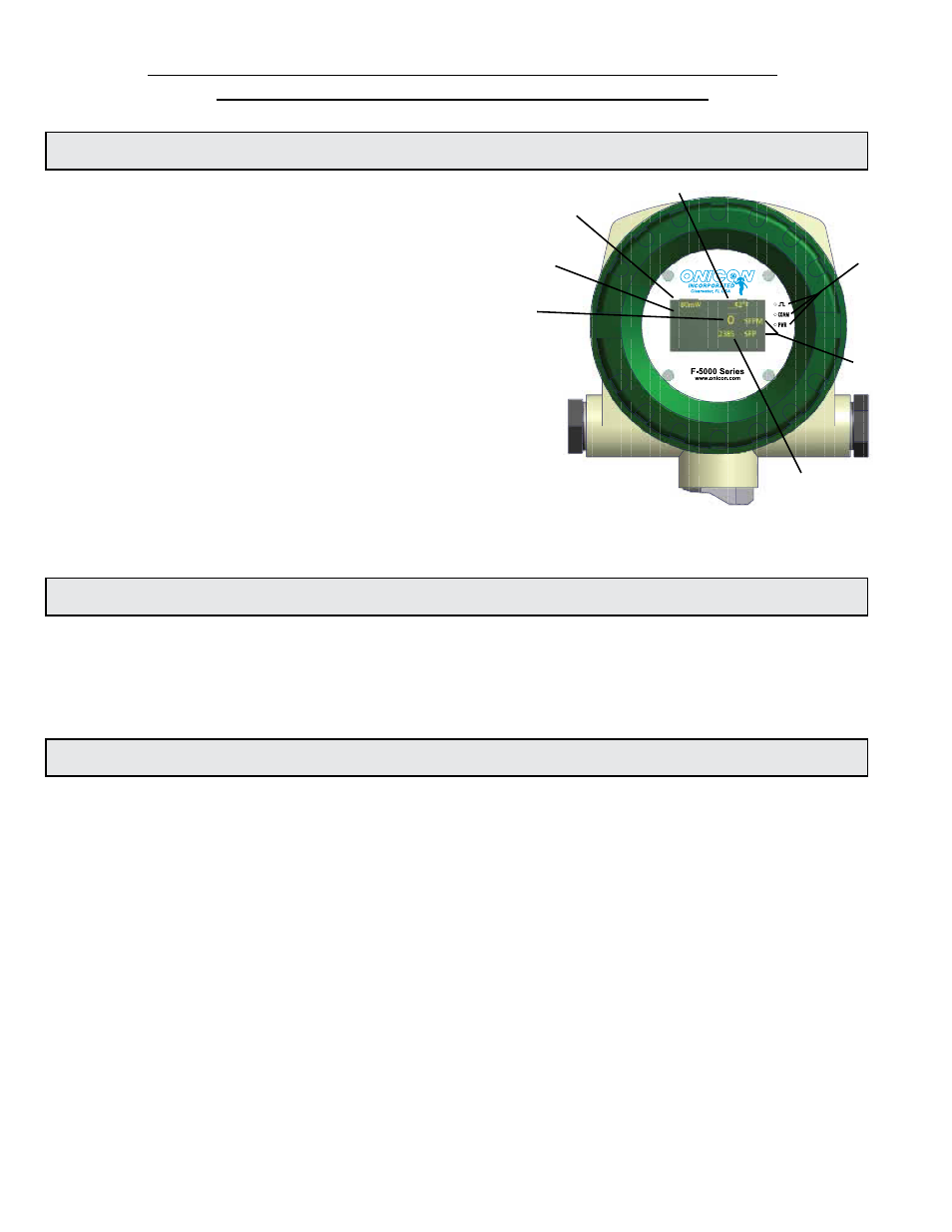
1
2
3
5
4
6
7
SECTION 4.0: START-UP & COMMISSIONING FOR ONICON
INSERTION THERMAL MASS FLOW SENSORS
4.1 DISPLAY
The F-5100 flow sensor features a bright easy-to-read
graphic LED display that displays alphanumeric and
graphical data.
This display is provided with a screen saver function
that extends the life of the display. The display will
revert to the normal display mode whenever the
proximity sensor detects movement directly in front
of the sensor.
Displayed Information:
1.
Energy reading used to validate calibration
2.
Graphical indication of percentage of full
scale flow rate
3.
Flow rate
4.
Flow total
5.
Fluid temperature
6.
Engineering units associated with flow rate and total
7.
LED’s for Power, Serial Communications, and Pulse Output
4.2 POWERING THE SENSOR
Upon initial power up, the sensor will indicate ONICON F-5000 Series along with the current
firmware version and the serial number. Two additional messages will be displayed and then the
sensor will advance to the normal run mode screen. If the sensor is installed in a pipe with flow,
the sensor will begin displaying flow and temperature data. After one minute of no movement,
the screen saver message will appear.
4.3 HELPFUL HINTS FOR START-UP & COMMISSIONING
A step-by-step procedure and companion worksheet are located on the next two pages. Please
read all installation instructions carefully before proceeding with start-up and commissioning.
Please read these helpful hints before proceeding with the start-up and commissioning procedure
on the next page.
1.
ONICON flow sensors are individually calibrated for a particular application. Be sure to
verify the pipe size and location.
2.
When measuring analog output signals, remember that current (mA) must be measured
in series, while voltage is measured in parallel. If the 4-20 mA signal is already connected
to a control system, you must break the connection and measure the signal in series.
3.
Do not attempt to rotate the electronics enclosure on the stem.
4.
Never connect power to analog or pulse output signal wires. Standard ONICON F-5100
Flow Sensors are not configured from the factory as “loop powered” devices.