4 installation instructions, 1 system layout, Installation instructions 4.1 system layout – REMKO WKF 85 User Manual
Page 36: Remko wkf / wkf-compact, Installation instructions, Ib ab, System layout
4
Installation instructions
4.1
System layout
IB
AB
IM1
NAM
KA1
STL
KML
NIM
NZ1
VWW
GRL
VHZ
AM1
VEN
STL
KML
IM2
NIM
NZ2
KA2
VRH
NAM
AM2
VEN
KA1
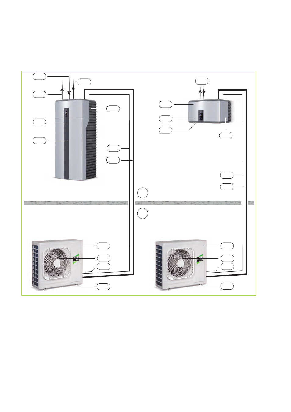
Fig. 36: System layout WKF/WKF-compact 85
AB:
Outdoor area
IB:
Indoor area
AM1,2:
Outdoor module WKF-compact 85, WKF
85
IM1,2:
Indoor moduleWKF-compact 85, WKF 85
GRL:
Common return pipe (DN 25)
KA1:
Condensate drain AM (must be designed
to be frost proof!)
KA2:
Condensate drain IM
KML:
Refrigerant lines
3
/
8
" and
5
/
8
“
NAM:
Mains supply AM = 230V / 1~ / 50Hz
16 A (e.g. 3x1,5 mm
2
)
NIM:
Mains supply IM = 230V / 1~ / 50Hz
16A (e.g. 3x1,5 mm
2
)
NZ1:
Mains cable electric auxiliary heater (e.g.
5x2,5 mm
2
)
NZ2:
Mains cable electric auxiliary heater
(optional), (e.g. 5x2,5 mm
2
)
STL:
Control cable (e.g. 2x1mm
2
)
VEN:
Fan
VHZ:
Inlet for heating (DN 25)
VRH:
Hot-water inlet and return pipes (DN 25)
VWW:
Inlet pipe for hot-water tank (DN 25)
REMKO WKF / WKF-compact
36