SoundTraxx DSD-150/DSX Owners Manual User Manual
Page 13
Digital Sound Decoder Owner's Manual
13
Geared engines require a larger number of chuffs due to multiple cylinders and gearing of the
drive wheels. Due to the large number of contacts required for each wheel revolution, it is usually
impractical to achieve the prototypically correct number of exhaust chuffs per revolution. The
Shay disk (supplied with the Exhaust Cam set) will provide a reasonable compromise. Optionally,
you may elect to use the Auto-Exhaust feature.
Install the Synchronizer Disk
Carefully measure the diameter of your locomotive's driver axle. Drill a hole of the same diameter
in the center of the synchronizer disk you plan to use.
Note: the thin disk material will be easier to drill if you
temporarily adhere it to a smooth wood block with a water soluble glue. The disk can be separated from the block by
soaking in water after the drilling operation is complete. Be sure to use a sharp drill to get a clean burr-free hole.
Once the hole is drilled, check that there is still enough foil at the 'hub' to connect all the spokes together. If not, you
will need to use a synchronizer disk with a large hub.
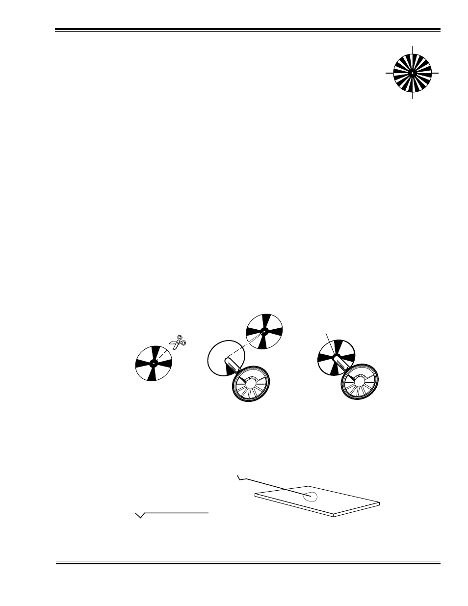
Cut the disk out with a sharp pair of scissors, and trim the disk diameter to slightly less than the locomotive drive
wheel diameter. This is important as clearance will be needed to clear turnout frogs, guard rails, and other trackwork
features.
Using the scissors, make a single radial cut in the disk between the foil spokes from the outer edge to the center
hole.Slip the disk over the drive axle with the insulated side facing against the drive wheel. Check for a correct fit and
make any needed adjustments. The disk should fit flush against the drive wheel and there should be a close fit
against the axle. Once you are satisfied with the fit, glue the disk against the
non-insulated drive wheel with epoxy or
contact cement.
You will need to electrically connect the sychronizer disk to the drive wheel axle. This is best done by soldering the
axle to the foil hub. Alternatively, you may use conductive paint to make the connection.
Figure 6 - Synchronizer Disk Installation
Install the Cam Wiper
Using the spring wire supplied with the Exhaust Cam set, fabricate a contact wiper. Bend the wire to match the
pattern of Figure 7 using a pair of needle nose pliers.
Figure 7 - Cam Wiper Fabrication
Solder the wiper to the small printed circuit board base as shown in Figure 7. Keep the spring wire as long as possible
1. Cut and trim
disk to fit
2. Glue disk to
uninsulated
driver
3. Solder disk
hub to axle
1. Bend spring wire
to this shape.
2. Solder to
mounting PCB