SoundTraxx DSD-150/DSX Owners Manual User Manual
Page 38
38
Digital Sound Decoder Owner's Manual
It isn’t necessary to solder any wires together during the test. Simply twisting the wires together will suffice.
We recommend insulating the ends of the decoder leads with electrical tape to prevent accidental shorts during the
testing.
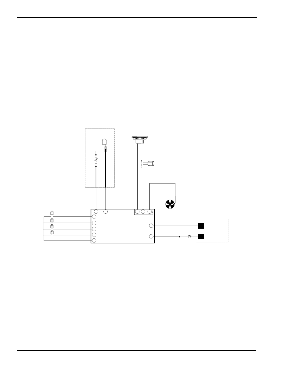
General Hookup
1.
Turn the power to the DCC system off.
2.
Select the lowest possible output voltage setting, usually the N-scale setting.
3.
Connect the decoder’s purple (pin 10) lead to the negative (-) terminal of the speaker.
4.
Connect the other purple lead (pin 12) to the positive (+) speaker terminal. A 100µF, 16V capacitor must be wired
in series as shown in Figure 2.
5.
Connect the red lead of the test LED to the decoder’s orange lead.
6.
Connect the black lead of the test LED to the decoder’s gray lead.
7.
Connect the 22 ohm resistor to one of your DCC system’s track outputs.
8.
Connect the free end of the resistor to the Decoder’s red wire.
9.
Connect the Decoder’s black wire to your DCC system’s other track output.
Figure 2 - General Hookup Procedure
Speaker Test
The objective of the Speaker Test is to ensure that the DSD is generating sound.
1. Make sure no other decoder leads are shorted to any other leads. The best way to do this is to simply tape the
other leads out of harm’s way while you are performing the test. Tape them to the non-metallic surface you are
working on until they are needed.
2. Turn on power to the system.
3. Configure your DCC system to send commands to locomotive address 03 using 28 speed step mode.
4. After a moment, you should hear the sound of airpumps and blowers running in the background. If you do not, turn
off power to the system and recheck your connections.
5. Activate Auxiliary Function 2. The Whistle should blow. Activate Auxiliary Function 3 and the bell should begin to
ring.
If the bell and whistle functions do not work, verify that your DCC system is indeed set to address 03. If your system
has dedicated bell and whistle keys, check that they are properly mapped to control Auxiliary Functions 2 and 3.
Gray
DCC BOOSTER
22 ohm
Resistor
TRACK
OUTPUTS
Red
Black
Orange
Bi-Color LED
Black Wire
Red Wire
1K ohm
Resistor
Speaker +
Speaker -
-
+
100
µ
F
16V
Purple
Purple
Brown
8
2
11
12
10
7
3
Function Common
Brown
Headlight
Backup Light
Function 1 Output
Blue
Yellow
White
Green
Function 5 Output
9
6
5
1
4
Cam