Step 2. plan the installation – SoundTraxx DSD-150/DSX Owners Manual User Manual
Page 6
6
Digital Sound Decoder Owner's Manual
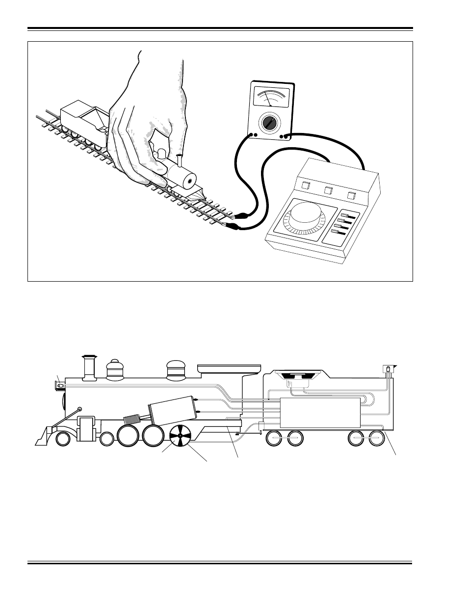
Figure 1 - Stall Current Test Setup
Step 2. Plan the Installation
You should give some thought to where the installation of the various DSD components will be within the locomotive
before you get started. Figure 2 shows a typical installation.
Figure 2 - Typical Sound Installation
The decision most critical to the success of your installation will be where to put the speaker. Obviously, the ‘where’
of speaker installation will depend on the size and type of the locomotive. But when considering the speaker’s
location, remember that the volume of the speaker will be greatly enhanced when the speaker is fitted into a small
airtight enclosure with the front of the speaker open to surrounding air. The reason for this is simple: in order to
generate any appreciable sound, the speaker must develop air pressure. Without an enclosure, any pressure devel-
;
;
;;;
;;;
;
;;
;;
;;;
;
;
;;;
;
;;
;
;;;
;
;
;
;;
;
;;;
;;;
;
;
;;;
;;
;
;;;
;
;;
;
;
;;;
;;
;;
;;;;
;;
;
;
;
;;;
;;;
;
;;;
;;
;;
;
;;;;
;
;
;
;
;
;
;;;
;;;
;
;;;
;
;
;
;;
;;;
;;;
;;;
;
;
;
;;
;;;
;
;
;;
;
;
;;
;
;;
;
;;;
;
;;;
;
;;;
;
;
;
;
;;
;
;;;
;
;;
;
;;;;
;;
;
;
;
;
;;
;;
;
;
;;
;
;
;;;;
;
;
;
;;;
;
;
;;
;
;
;
;
;;
;;
;;;;
;
;
;;
;;
;;
;
;;
;;
;
;
;;
;
;;
;;
;
;
;
;
;
;;
;
;
;;
;;;
;
;
;
;
;;;
;
;
;
;
;
;
;
;;
;
;
;;
;
;;
;;
Ammeter
DC Power Pack
set to 12V
(16V for G-Scale)
Backup Light
Right Rail Pickup
usually connects
to locomotive frame
Headlight
Synchronizer
Disk
Digital
Sound
Decoder
Speaker
Exhaust Cam
Left Rail Pickup
usually connects
to tender frame
Blue
White
Motor (+) Lead
Motor (-) Lead
Red
Gray
Orange
Purple
Purple
Black
Yellow
Blue