Step 4. fit the speaker – SoundTraxx DSD-150/DSX Owners Manual User Manual
Page 9
Digital Sound Decoder Owner's Manual
9
STOP
Failure to properly isolate the motor will damage your decoder and turn it into an effective, but short
lived smoke generator!
Our warranty specifically excludes damage caused by improperly isolating the motor; however, in the event you do
damage your decoder, simply return it to Throttle Up! along with the service fee (please call for current amount) and
we will repair and return it promptly.
Begin motor isolation by removing the boiler and tender shell from the locomotive and tender frame.
Before you proceed further, it is important to carefully examine the locomotive wiring and determine where each wire
goes and what it does. The manufacturer’s assembly drawings may be useful here or you may elect to create your
own wiring diagram. In particular, you will need to identify the connections to the left and right power pickups as well
as the (+) and (-) motor connections. Note: for N, HO, S and O scale locos, the positive motor connection is the one
connected to the right rail (engineer side) power pickup. On G scale locos, the positive motor lead is connected to the
left rail pickup (fireman side).
Disconnect all wires leading to both motor terminals. Note that some motor brush connections are made using a
spring contact to the chassis. In such cases, it will be necessary to remove or modify the spring contact as well. Be
aware that some locomotives may make contact between the motor and frame only when the body is reinstalled.
Next, verify that each motor terminal is electrically isolated from the left and right rail pickups using an volt-
ohmmeter or continuity tester. With your meter set to the ohms scale, touch both meter probes together and note that
the meter indicates 0 ohms (short circuit). You don’t want to see this indication again! Touch one of the probes to one
of the motor brush terminals. Touch the other probe to the locomotive frame, then the left rail power pickup wire, and
finally to the right rail power pickup wire. Move the first probe to the other motor brush terminal and repeat the tests.
If all tests indicate an open circuit, the motor is properly isolated. Do not proceed further until this is done.
You will also need to disconnect the wires leading to any lights you wish to use. If you plan to use the Full-Wave
method of lamp wiring (see page 15), you must disconnect and isolate both lamp wires. Using an ohmmeter, check
that each lamp lead is electrically isolated from the frame as well as the left and right rail pickups.
If you choose to use the Half-Wave method of lamp wiring (see page 15), leave one lamp lead connected to the
locomotive frame or tender chassis provided the frame or chassis is electrically connected to the proper power
pickup. This will allow you to use existing lamp sockets if your engine is so equipped. See Step 8, page 15 "Lighting
Outputs" for specific details.
Step 4. Fit the Speaker
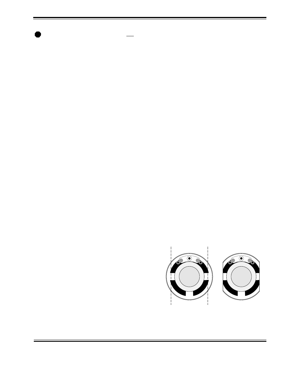
If the speaker is wider than the tender, it will be necessary to
reduce the speaker width to get a proper fit. Determine how
much the speaker must be cut down and remove half of that
amount from each side of the speaker.
Speakers with plastic frames may be trimmed down using a
sharp flat file. File down the speaker sides - work slowly and
alternate from side to side until the speaker just fits within the
tender shell. Be careful to remove only the speaker frame and
outer edge of the diaphragm. Avoid cutting into the diaphragm
itself.
Speakers with metal frames can generally have a larger amount
of frame and speaker cone removed and still maintain a satis-
factory sound. On the back of the speaker frame, draw a line
where the first cut will be made. Draw a second, parallel line
Cut equal amounts
from each side.
Figure 3 - Modifying the Speaker