Appendix b - dsd functional test – SoundTraxx DSD-150/DSX Owners Manual User Manual
Page 37
Digital Sound Decoder Owner's Manual
37
APPENDIX B - DSD FUNCTIONAL TEST
Although each DSD has been fully tested prior to shipment and is ready for installation, we urge you to test your
decoder before installing in your locomotive! We have developed a simple procedure that assures you that the DSD
is functioning as it should before you do the installation. If this is your first sound or decoder installation, it will give you
an added boost of confidence, knowing that as long as you follow the installation instructions...it
will work!
In the event you do have a problem, please contact your dealer or Throttle Up! for technical assistance first. We will
gladly refund payment or replace any decoder that does not pass the functional test free of charge provided that
none of the decoder wires have been cut short.
Before you get started, we must reiterate -
do not shorten any decoder leads until you have verified that the decoder
is functioning properly.
Do not install any decoder that does not pass the Functional Test.
Items Needed for the Functional Test
To perform the Functional Test, you will need:
A Decoder Test Kit
An NMRA-compatible DCC system
One 8 ohm speaker
Creating a Test Kit
For your convenience, Throttle Up! offers a test kit, Item No. 829001 which includes all of the items needed for testing
the DSD, including detailed instructions. If you prefer, you can make up your own kit with some simple parts pur-
chased from your local electronics supplier. If you decide to create your own test kit, you will need:
Qty.
Description
1
Resistor, 22 ohm, 2 Watt
1
Resistor, 1K ohm, 1/4 Watt
1
Bicolor LED
1
Black Wire
1
Red Wire
Length of small diameter shrink tubing
Preparing the Test Fixture
1.
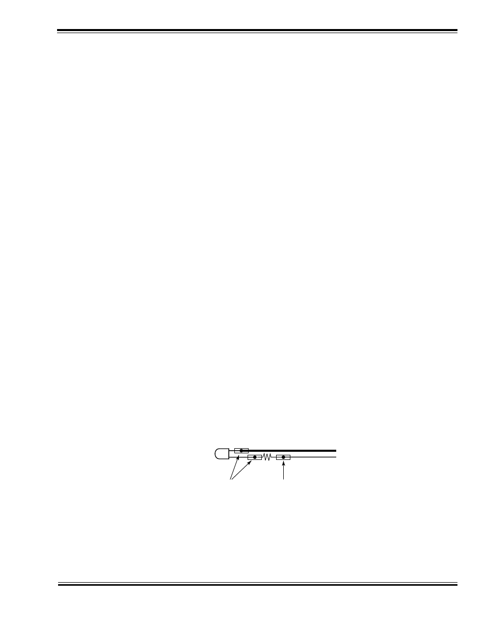
Connect the black wire to the short lead of the LED.
2.
Connect one lead of the 1K ohm resistor to the long lead of the LED.
3.
Connect the other lead of the 1K ohm resistor to the red wire.
4.
Insulate the connections with heat shrink tubing.
5.
Verify the LED is working properly by connecting the red lead to the positive (+) terminal of a fresh 9 volt battery
and the black lead to the battery’s negative terminal. The LED should glow red. Reverse the leads and note that
the LED color changes to green.
Preparing the Decoder Test Kit
DSD Functional Test Procedure
Follow directions carefully, working on a
non-metallic surface.
Any NMRA-compatible DCC system will work for the test. Consult your system manual for appropriate operating
instructions.
Bi-Color LED
Flat side of LED
(short lead)
Black Wire
Red Wire
1K ohm
Resistor
Insulate connections with
heat shrink tubing