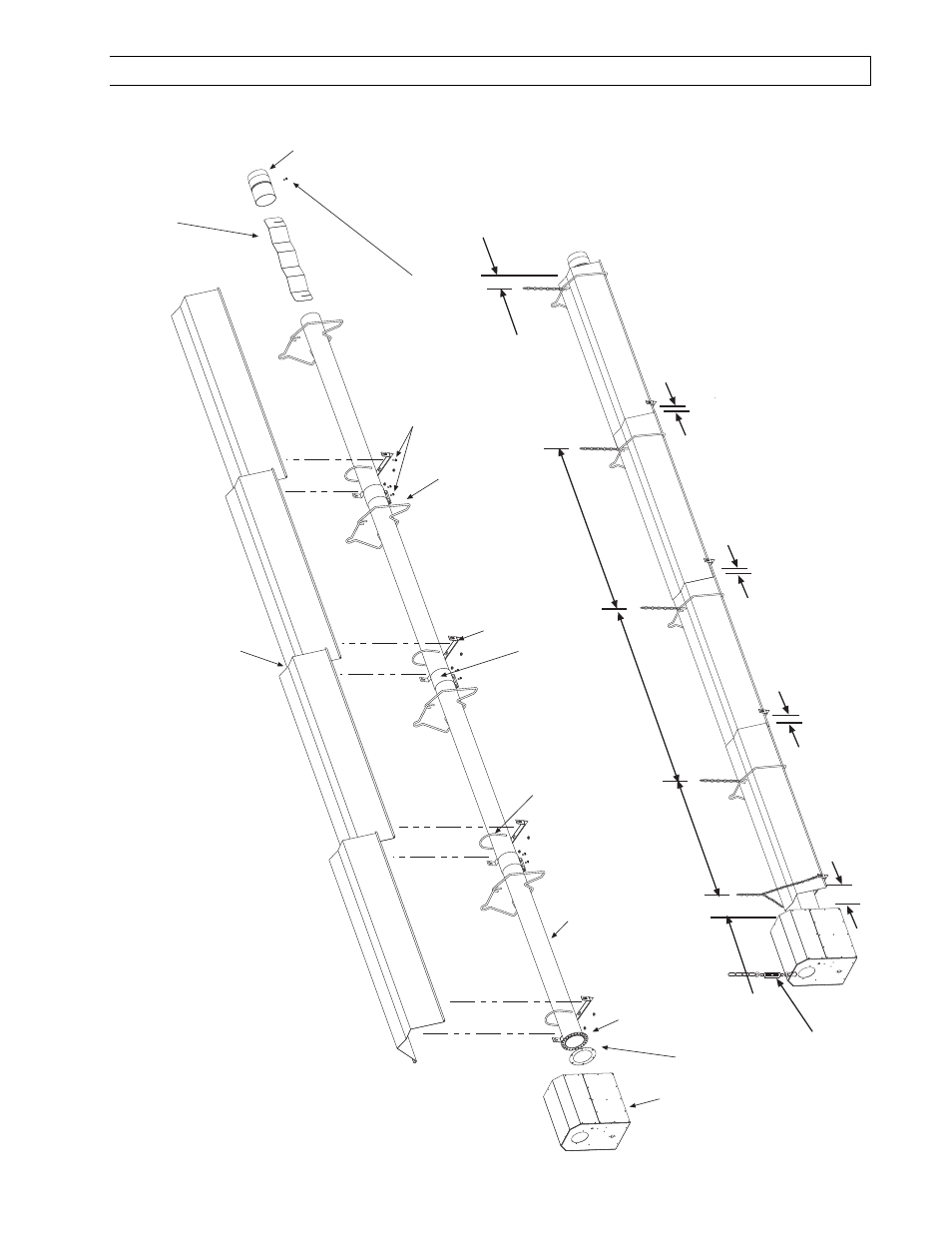
Typical assembly overview, 40ft shown) – Space Ray PTS Series Single Stage User Manual
Page 17
Form 43343330
-16-
Aug 2012
8.2)
HEATER ASSEMBLY / JOINING OF TUBE SECTIONS
T
ypical
Assembly Overview
(
PTS
40FT
Shown)
4"OD x 10Ft.
T
ube
See section
7
for required tubes.
T
ube Support Bracket
U-Bolt Clamp &
5/16" Hex Nut
s
Mounting
Flange
24 Hole for
Aluminized S
teel
T
ubes
6 Hole for
Alumi-Therm S
teel
T
ubes
Wire Hanger
Gasket
Burner
Box
Flue
T
erminal
5 hanging point
s to be used for suspension for a typical 40f
t
long system.
There must be two hanging point
s on the first
tube and one on each of the other tubes
Maximum 6 dist
ance
from control box to the
tube support/hanger
bracket.
8
- 9
¼
8
- 10
8
- 10
Not More Than 10
#10 Self-Drill Screws
(T
ypical all tube support
s,
tube couplings and flue
terminal.)
T
ypical
Overlap
T
urbulator
(See specifications
section 5 for required
quantities.)
T
ube Coupling
(T
ypical each tube joint
.)
Burner Box
Suspension
Chain
3
(burner
box to reflector)
2
overlap
1
overlap
1
overlap