Space Ray PTS Series Single Stage User Manual
Page 39
Form 43343330
-38-
Aug 2012
3.
Use the following correction factors to obtain the equivalent length when elbows are used:
•
Subtract 10 ft. for each elbow beyond 15 ft. from the heater.
•
Subtract 15 ft. for each elbow within 15 ft. of the heater.
4.
Limit to (2) 90º elbows in the vent system.
5.
When venting through a sidewall, the horizontal vent pipe shall fall not less than 1/2 inch per 20 feet from
the start of the vent system to the vent terminal. All portions of the vent pipe shall be supported to prevent
sagging. (6’ spacing is recommended)
6.
A minimum clearance of 6 inches must be maintained between the outside wall and vent cap (18”
clearance will provide stability under high wind conditions).
7.
The horizontal venting system shall not terminate:
•
Less than 4 ft. (1.2m) below, 4 ft. (1.2m) horizontally from or 1 ft. (30cm) above any door, operable
window or gravity air inlet into any building. The bottom of the vent terminal shall be located at least 7
ft. (2.1m) above grade or above snow accumulation level as determined by local codes.
•
Less than 3 ft. (0.9m) from a combustion air inlet.
•
Less than 3 ft. (0.9m) from any other building opening or any gas service regulator.
•
Less than 7 ft. (2.1m) above public walkways.
•
Directly over areas where condensate or vapor could create a nuisance or hazard or be harmful to the
operation of gas utility meters, regulators, relief valves, or other equipment. Building materials should
be protected from flue gases and condensate.
•
Less than 18” (0.45m) when directly below a combustible overhang.
8.
In regions of the country where prevailing winds are consistently higher than 40 mph, it may be necessary to
terminate the vent system above the roof level.
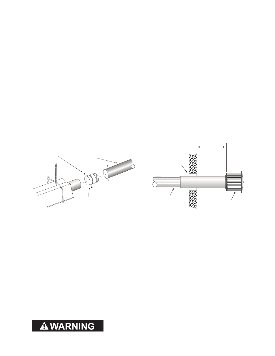
Flue Adapter
Collar
#10 Self-Drill
Screws
(typical)
4 Vent Pipe
(horizontal position)
Vent Cap
(Part #30297040)
2 (5cm)
Clearance
Thimble
1/2 (12mm) fall per 20 ft
(6m) toward vent terminal
6 (15cm)
minimum
MULTIPLE HEATER VENTING (CONNECTIONS INTO A COMMON VENT OR MANIFOLD)
MULTIPLE HEATER VENTING (CONNECTIONS INTO A COMMON VENT OR MANIFOLD)
MULTIPLE HEATER VENTING (CONNECTIONS INTO A COMMON VENT OR MANIFOLD)
MULTIPLE HEATER VENTING (CONNECTIONS INTO A COMMON VENT OR MANIFOLD)
Requirements for venting of multiple heaters are the same as described for SINGLE HE
SINGLE HE
SINGLE HE
SINGLE HEATER VENTING
ATER VENTING
ATER VENTING
ATER VENTING except as
follows:
1.
The common vent size and total vent height is normally determined by the number of heaters per common
vent, length of horizontal connector runs, and connector fall. Connector lengths should be as short as
possible and have a minimum 1/2 inch per 20 foot fall. Without regard to connector fall and total vent
height due to many possible venting configurations, the following should be observed:
•
Common vent pipe & vent connector diameter should be no less than that shown in the following Vent
Sizing Table.
•
The connector length should be no more than 75% of the vertical portion of vent above the connector.
•
Where possible, use a Y-connector to the common vent.
2.
Material for connectors should be constructed of galvanized sheet metal or other approved noncombustible
corrosion resistant material as allowed by state or local codes. All common vent pipe should be insulated
flue pipe or double wall, Type B vent.
3.
Avoid unnecessary bends. Limit to two (2) 90º elbows.
4.
The entire length of vent connector shall be readily accessible for inspection, cleaning and replacement.
5.
Groups of heaters with a common vent must be controlled by a common thermostat.
If any heater connected to a common vent system for multiple
If any heater connected to a common vent system for multiple
If any heater connected to a common vent system for multiple
If any heater connected to a common vent system for multiple
heaters is found inoperative, t
heaters is found inoperative, t
heaters is found inoperative, t
heaters is found inoperative, the heater should be disconnected from
he heater should be disconnected from
he heater should be disconnected from
he heater should be disconnected from
the vent system and its entrance into the vent system capped.
the vent system and its entrance into the vent system capped.
the vent system and its entrance into the vent system capped.
the vent system and its entrance into the vent system capped.