0) air for combustion, 1) direct outside air for combustion – Space Ray PTS Series Single Stage User Manual
Page 41
Form 43343330
-40-
Aug 2012
B.
B.
B.
B.
INDIRECT VENTING (UNVENTED HEATERS)
INDIRECT VENTING (UNVENTED HEATERS)
INDIRECT VENTING (UNVENTED HEATERS)
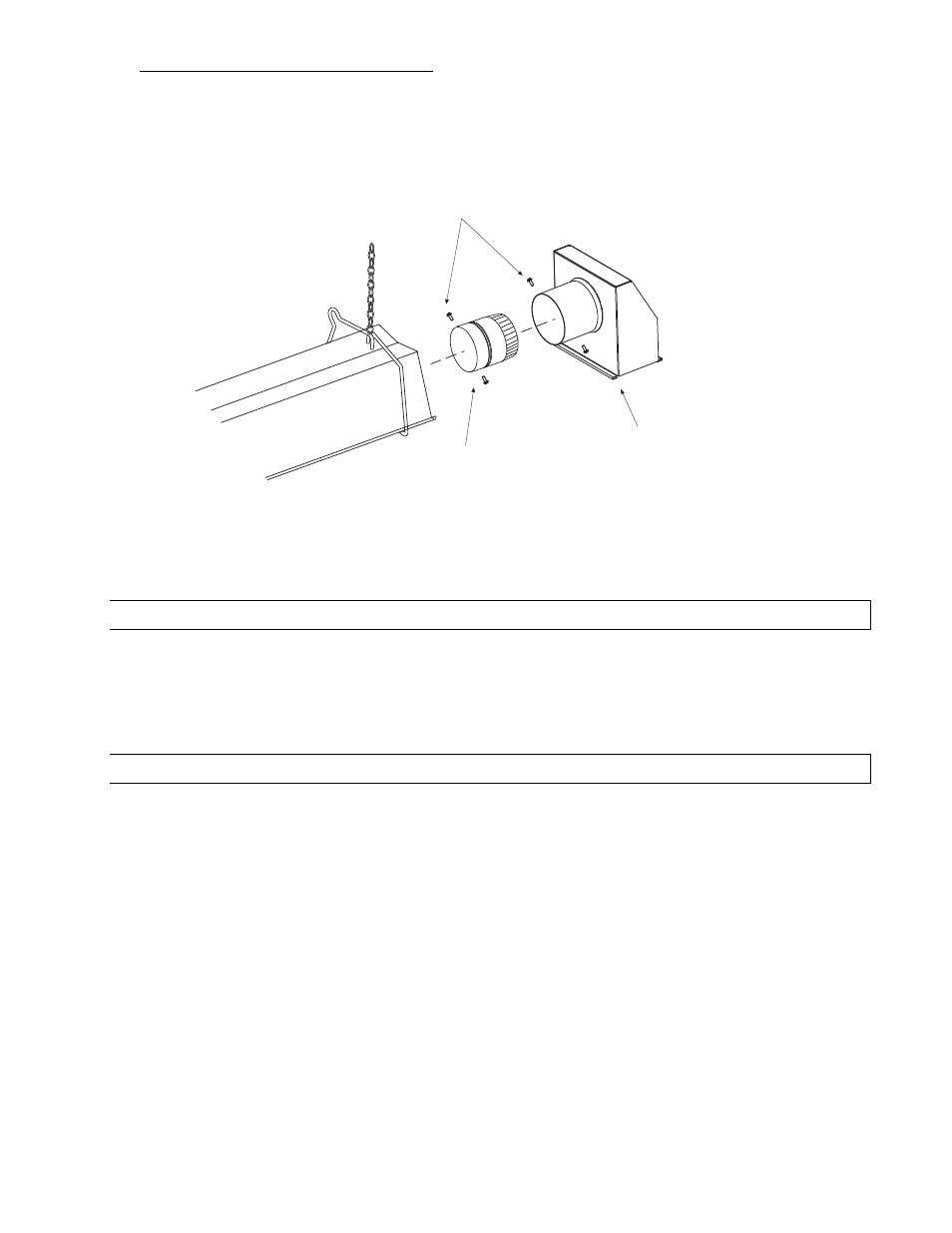
INDIRECT VENTING (UNVENTED HEATERS) — This heater requires ventilation in the building to dilute the
products of combustion and provide fresh air for efficient combustion. Where unvented heaters are used,
gravity or mechanical means shall be provided to supply and exhaust at least 4 CFM per 1,000 Btu/hr input
of installed heaters. Exhaust vents must be located at the highest point above and in the vicinity of the
heaters, and the inlet vents must be located below the level of the heaters. An exhaust hood (Part
#42924000) must be placed on the flue adapter collar located on the end of the last body section when
used unvented and must be mounted only in a downward posit
must be mounted only in a downward posit
must be mounted only in a downward posit
must be mounted only in a downward position as shown.
ion as shown.
ion as shown.
ion as shown.
Flue Adapter
Collar
Exhaust Hood
(mount in a downward
position)
#10 Self-Drill
Screws
Exhaust Hood Attachment
(for UNVENTED use)
17.0)
AIR FOR COMBUSTION
If indoor combustion air is to be supplied for a tightly enclosed area, one square inch of free area opening shall
be provided below the heater for each 1,000 Btu/hr of heater input. When outside air is used, the opening below
the heater shall be one square inch of free area for each 4,000 Btu/hr of heater input. In contaminated
atmospheres or high humidity areas, optional outside air for combustion is recommended. Adequate clearances
around the air inlet screen must be maintained at all times. In larger open areas of buildings, infiltration
normally is adequate to provide air for combustion.
17.1)
DIRECT OUTSIDE AIR FOR COMBUSTION
Outside combustion air should be supplied directly to the heater when the building is subject to negative
pressure, or when contaminants or high humidity are present in the building air. These contaminants include
paints, solvents, corrosive vapors or any other foreign particles that may cause damage to the heater or result in
poor combustion.
Outside combustion air can be brought directly to the heater by a 4” diameter duct less than 50 ft. long or
equivalent (see table in Section 16.0) based on selected model and heat exchanger lengths). This is attached to
the 4” diameter starting collar (supplied with heater). The starting collar is fitted to the rear of the burner box
cabinet as shown below. An approved vent cap must be placed directly on the end of the outside combustion air
inlet pipe. The combustion air inlet should be not less than 3 ft. (0.9m), either vertically or horizontally, from the
flue vent termination. The air intake terminal must be located not less than 1 ft. (30cm) above grade. It is good
installation practice to supply combustion air from the same pressure zone as the vent outlet. Avoid bringing
combustion air to the heater from an attic space. There is no guarantee that adequate combustion air will be
supplied.
If the heater is installed less than 2 ft. from the ceiling, a combustion air inlet kit PN 44129510 must be
provided to allow for expansion/contraction of straight tube heaters (PTS series).
In colder climates, where necessary, insulate the outside combustion air duct. In high humidity applications, the
burner box should be sealed with silicone sealer.