Internal connection wiring diagram, Schematic – Space Ray PTS Series Single Stage User Manual
Page 35
Form 43343330
-34-
Aug 2012
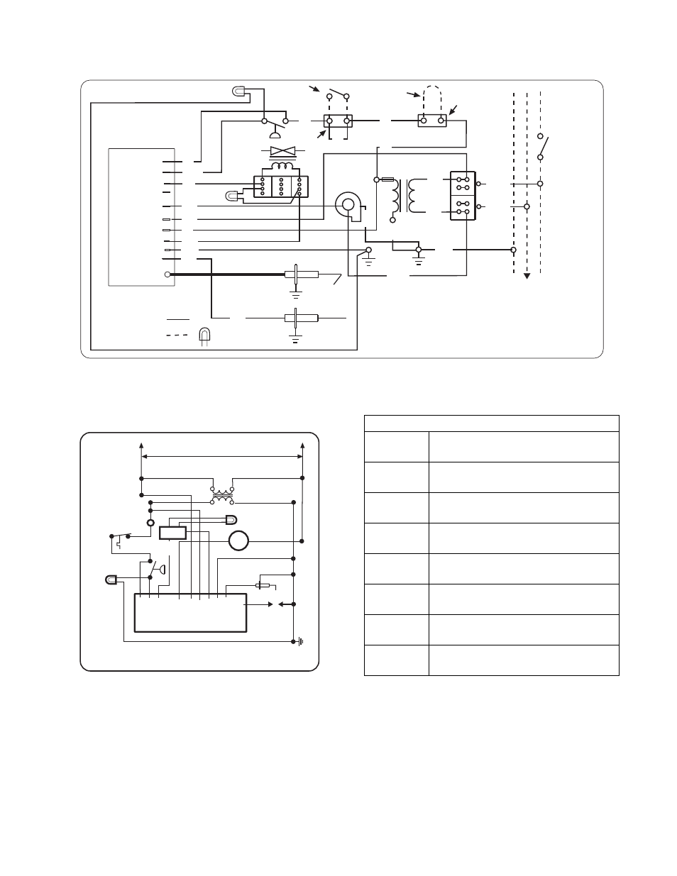
INTERNAL CONNECTION WIRING DIAGRAM
INTERNAL CONNECTION WIRING DIAGRAM
INTERNAL CONNECTION WIRING DIAGRAM
INTERNAL CONNECTION WIRING DIAGRAM —
—
—
—
Direct Spark Ignition
Direct Spark Ignition
Direct Spark Ignition
Direct Spark Ignition
Draft Inducer
Motor
Gas Valve
Air Switch
Transformer
Primary 120V
Secondary 24V
High Voltage Cable
Electrode
Gap 1/8
CONTINUE TO
ADDITIONAL
HEATERS
Terminal Block
CONNECTION WIRING DIAGRAM
If any of the original wire as supplied with the
appliance must be replaced. It must be
replaced with wiring material having a
temperature rating of at least 105oC. (18
AWG. - UL / CSA 600V Type TEW)
When connecting the supply circuit to the
heater, wiring material having a minimum size
of 14 AWG and a temperature rating of at
least 90oC shall be used.
Schéma de circuit de connexion
Vers les autres
radiateurs
Plaque à
bornes
Transformateur
bobine primaire 120ÊV
bobine secondaire 24ÊV
pressostat
Robinet à gaz
Écartement
d'électrode
3,2Êmm
Haute tension
Bloc d'allumage
Moteur
d'amorce
d'aspiration
GND
V2
V1
(W)TH
Ignition Module (Fenwal)
(R) 24VAC
L1
IND
NC
P.SW
HV
S1
Flame Sensor
FACTORY WIRING
FIELD WIRING
Circuit d'origine
Connexions client
L2 NEUTRAL
L1 (hot) 120V
THERMOST
A
T
(line volt
age)
GROUND
MONITORING LIGHTS
Lampes témoins
42874020 Rev F 1/2011
Red
Light
Amber
Light
L1 Black
L2 Black
(ribbed)
Black
White
Black
(ribbed)
Black
Green
Violet
Orange
Red
Green
Violet
Black
White
Red
Blue
White
Fuse 2A
Fusible
Optional Low
Voltage (24V)
Thermostat
Remove jumper wire.
Red
Red
(jumper)
Terminal
Block
TISS
(Tube Integrity
Safety Switch)
Red
Terminal Block
Plaque à
bornes
Red
Green
Terminal
Block
SCHEMATIC
SCHEMATIC
SCHEMATIC
SCHEMATIC WIRING DIAGRAM
WIRING DIAGRAM
WIRING DIAGRAM
WIRING DIAGRAM
IIIIGNITION MODULE TERMINAL DESIGNATIONS
GNITION MODULE TERMINAL DESIGNATIONS
GNITION MODULE TERMINAL DESIGNATIONS
GNITION MODULE TERMINAL DESIGNATIONS
SCHEMATIC WIRING DIAGRAM
42785020 03/08
120V
GND
V2
V1
(W)TH
24V
AC
L1
IND
NC
P
.SW
HV
S1
MV MV
Motor
Transformer
24V
Igniter
Flame
Sensor
Ignition Module
Air
Switch
Thermostat
TISS
Red
Light
Gas
Valve
Amber
Light
24VAC/R
24 VAC Supply to Module
TH/W
Thermostat Input
PS/W
Pressure Switch Input
GND
System Ground
V1
Valve Power
V2
Valve Ground
L1
120/240 VAC Input (Hot)
IND
Blower Output
NOTES:
NOTES:
NOTES:
NOTES:
1.
If any of the original wire as supplied with the appliance must be replaced, it must be replaced with wiring
material having a temperature rating of at least 105ºC. (18 Ga. CSA 600V Type TEW)
2.
When connecting the supply circuit to the heater, wiring material having a minimum size of 14 AWG and a
temperature rating of at least 90ºC shall be used.