Flow alarm – Super Systems eFLO User Manual
Page 13
eFlo Electronic Flow Meter Operations Manual
Super Systems Inc.
Page 13 of 25
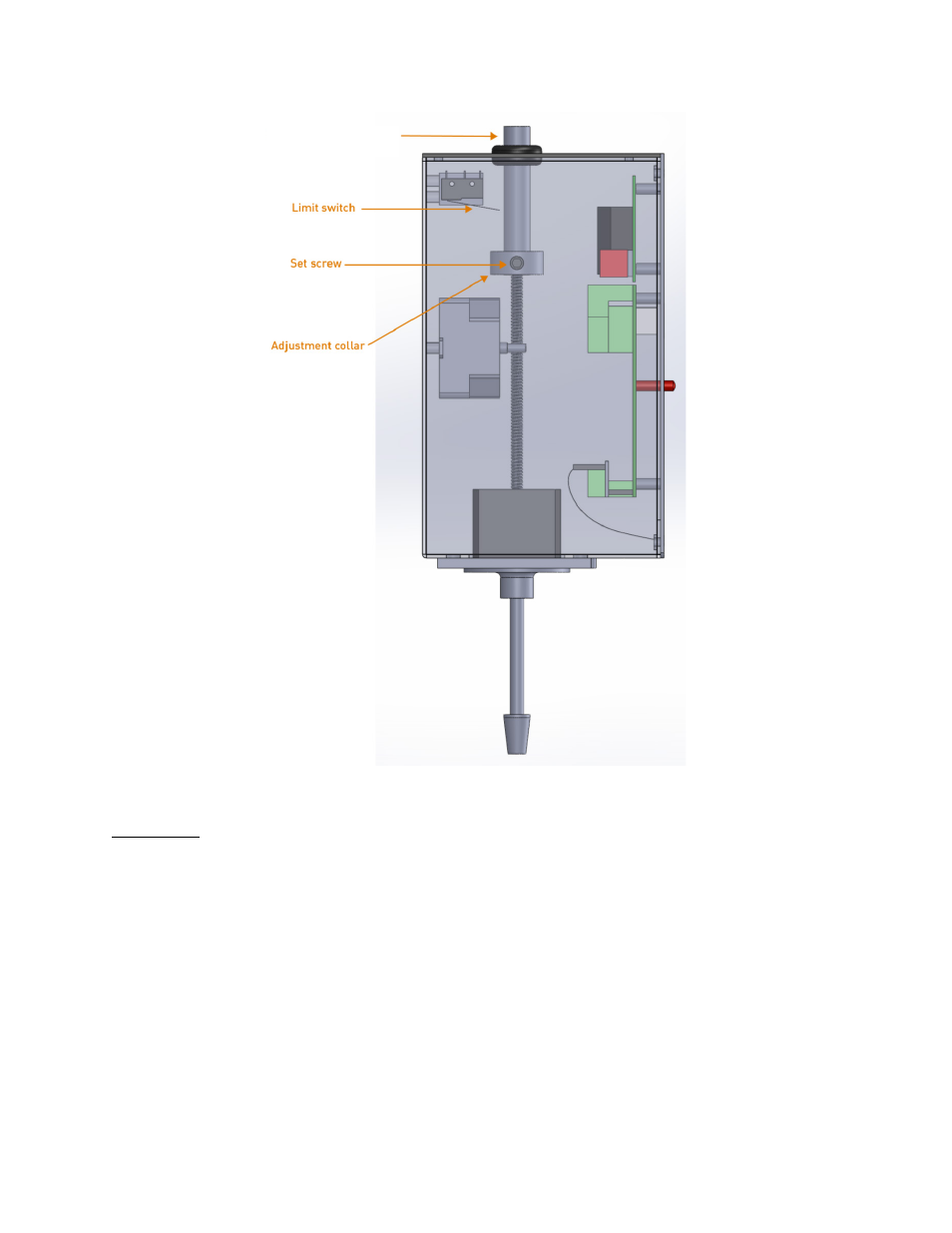
Figure 4 - Location of Manual Adjustment Cylinder, Set Screw, and Adjustment Collar
Flow Alarm
The eFlo meter incorporates a High Flow Alarm and Low Flow Alarm. Setpoints for these
alarms are set through a Modbus interface or by using SSi’s FlowMeterView software (provided
free of charge to eFlo users).
When the alarm is active, the Alarm light will turn on. A warning message will be displayed on
the LED screen.
In order to function properly, the flow alarm setpoints must be set prior to use of the eFlo unit,
and the alarm must be wired properly. The alarm current should have a maximum current
rating of 100mA. An isolation relay with fly-back diode should be used if the output is driving an
inductive load (such as a contactor or horn). See Appendix 1: Electrical/Wiring Diagram for
more information on wiring.
Adjustment cylinder