Electrical connections – Super Systems eFLO User Manual
Page 7
Advertising
eFlo Electronic Flow Meter Operations Manual
Super Systems Inc.
Page 7 of 25
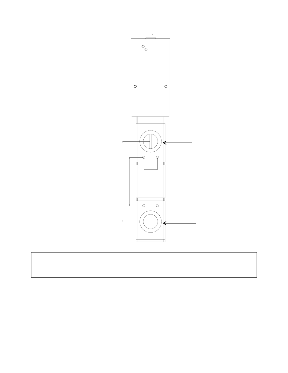
Figure 2 - Flow Outlet and Inlet Connections
IMPORTANT!
Ensure that the inlet pressure is within specified parameters for your eFlo unit.
Electrical Connections
The eFlo unit uses a male 9-pin D-Sub connector for electrical connections. The electrical
connections are defined in Table 3 below. (An electrical/wiring diagram for the flow control
board can be found in Appendix 1: Electrical/Wiring Diagram.)
8.
30
5.
00
1.40
Outlet Connection
(Opening: 1.25” NPT)
Inlet Connection
(Opening: 1.25” NPT)
Advertising