Replacement parts – Super Systems eFLO User Manual
Page 5
eFlo Electronic Flow Meter Operations Manual
Super Systems Inc.
Page 5 of 25
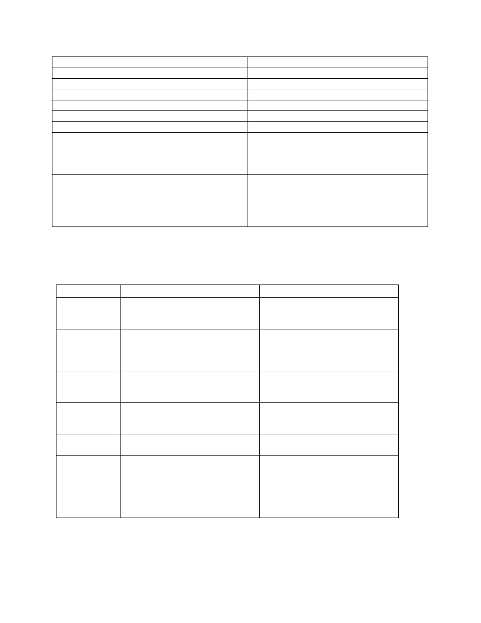
Ambient Temperature Limits
-10°F to 150°F (-20°C to 65°C)
Flow Output Signal (Linear)
4-20mA
Maximum Output Signal Load
500
Ω
Input Control Signal (Linear)
4-20mA
Response Time
1 – 10 seconds
Communications
RS232, RS485
Communication Protocol
Modbus RTU
Pressure Drop @ 100% Capacity
See Calibration Report for specific pressure
drop.
5” wcg (Standard Model)
10” wcg (Standard Model)
Flow Meter Pressure Limits
The pressure will be calibrated to user-
specified requirements. See the Calibration
Report for more details.
5 psig – maximum allowable
Table 1 - eFlo Specifications
Replacement Parts
Replacement parts can be ordered for the eFlo unit when and if needed. Contact SSi at (513)
772-0060 to order parts.
Part Number
Item
Explanation
33149
Motor and Shaft
Drives the Valve Needle open and
closed to maintain the correct gas
flow.
34224
O-Ring, eFlo Body & Plate
O-ring that seals the three
components of the eFlo Body
(upper, lower, and middle),
Bottom Plate, and Motor Plate.
37315
O-Ring, eFlo Valve Needle Shaft
O-ring that seals the Valve
Needle Shaft against the Motor
Plate.
37321
Gasket, eFlo Motor Plate
Gasket that seals the eFlo Motor
Plate to the Motor Spacer Block
and Motor.
34603
Grommet, Cylinder Adjustment
Grommet on top of the Electronic
Housing.
34692
Calibration Test Ports
Two pressure ports located on
the side of the Body of the meter.
These ports allow the pressure
drop to be measured for
calibration verification of the
meter.