Modbus registers – Super Systems eFLO User Manual
Page 8
eFlo Electronic Flow Meter Operations Manual
Super Systems Inc.
Page 8 of 25
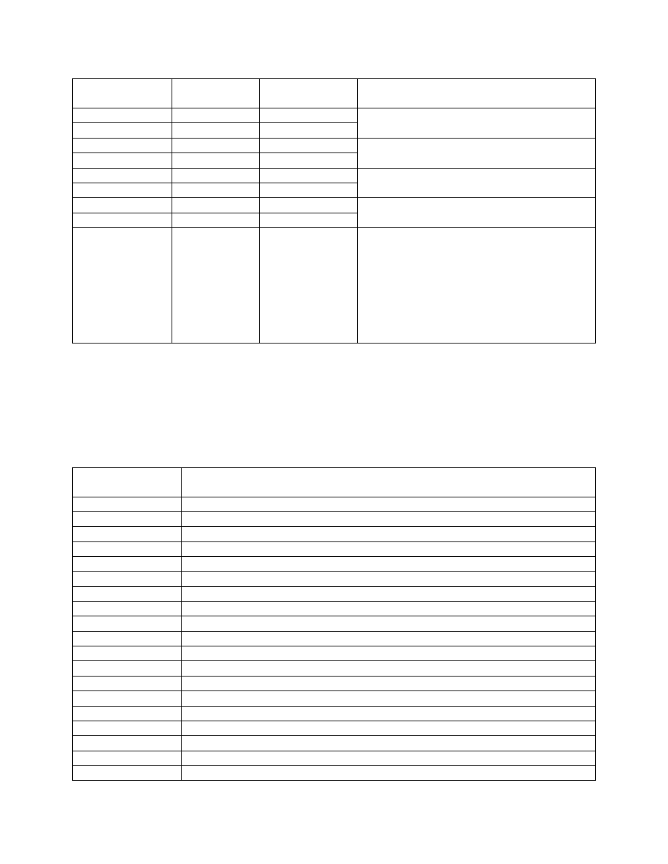
9-Pin D-Sub Pin
Number
Wire-In Color
Signal Type
Description
1
Red
+ VDC
Power Supply 24 VDC (250 mA)
2
Black
- VDC
3
Green
+ mA
Output Flow Signal (4 – 20 mA)
4
White
- mA
5
Orange
+ mA
Input Setpoint Signal (4 – 20 mA)
6
Blue
- mA
7
Brown
+ RS485
Communications Signal provided by
Modbus over serial.
8
Yellow
- RS485
9
Purple
24V Sinking
Output
Flow Alarm Output
NOTE: The alarm current should have a
maximum current rating of 100mA. An
isolation relay with fly-back diode should
be used if the output is driving an
inductive load (such as a contactor or
horn).
Table 3 - Electrical Connections
NOTE: If RS-232 is needed, an additional 9-pin D-Sub connector can be set up on the eFlo unit
prior to shipment.
Modbus Registers
The eFlo Modbus registers are as follows.
Modbus Register
Number
Description
16
Actual Flow
17
Flow Sensor mA Input Value
18
Flow Setpoint
19
Decimal Place for Display of Flow and Setpoint
20
Instrument Modbus Address
21
Flow Meter Full Scale Value
22
Control Gain
23
mA Zero Value
24
mA Span Value
25
Deadband for Control
26
Setpoint Zero
27
Setpoint Span
28
Not Used
29
Analog Output Zero in Flow Units
30
Analog Output Span in Flow Units
31
Not Used
32
Low Flow Alarm Setpoint
33
High Flow Alarm Setpoint
34
Alarms